Mooring system
Manuals
Mooring system
Table of Contents
1 Summary with components overview and key points related to prevention of escape, with illustrations and pictures
1.1 General description of the ScaleAQ mooring system
ScaleAQ mooring system consists of a grid with mooring lines and bridles. All is connected through connection points. See Appendix 8 for AQ Ring as a connection point.
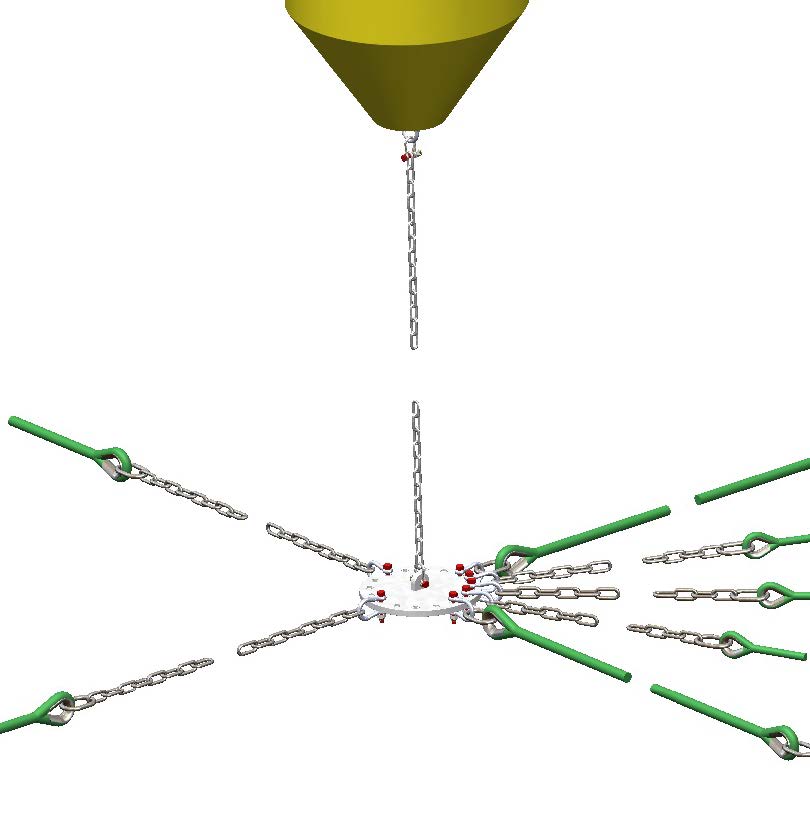
The mooring system is pretensioned to avoid shock loads. Buoys are used for buoyancy to achieve this pretension. Because of this the mooring system will work regardless of whether the pens are installed or not. The design of the connection point is shown in figure 1 with shackles used for connecting the buoy chain, grid ropes, bridles and anchoring lines.
1.2 Maximum permitted load
For the maximum permitted load on mooring components, see the product certificate for each component.
1.3 Use of mooring components
Mooring components can be used for mooring pens and barges. See NS 9415:2021 for definitions of therms.
1.4 Anchoring lines
Anchor lines are designed as shown in figure 2. The numbering refers to the section in which the individual component is described.
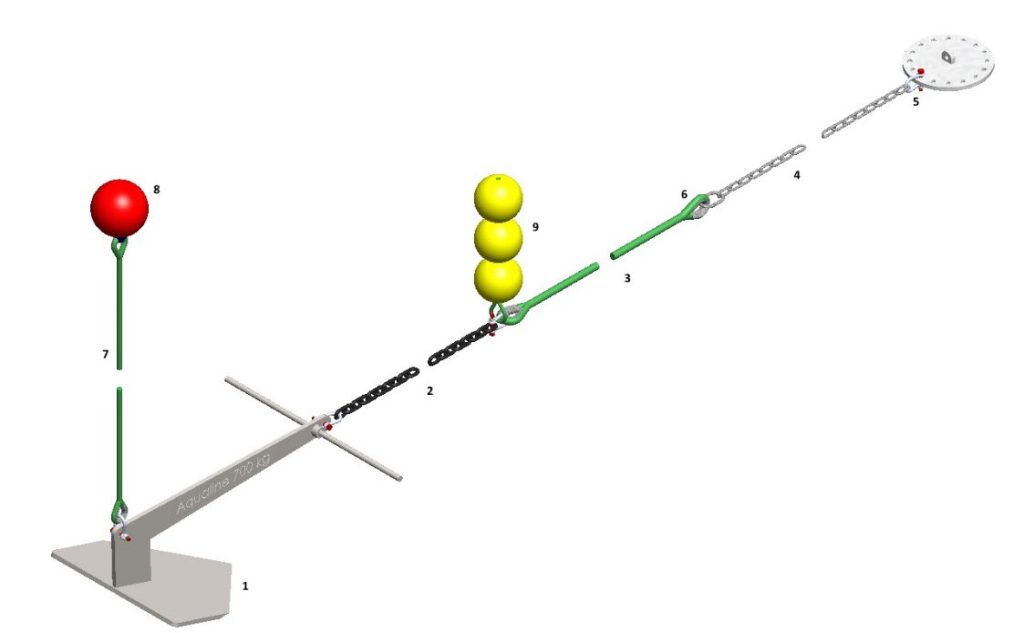
An anchoring line consists of the following components:
- Anchor or rock bolt
- Ground chain
- Rope
- Chain sling or Master link
- Shackle
- Thimble
- Float line
- Floater
- Trawl floats (Optional)
1.5 Grid rope
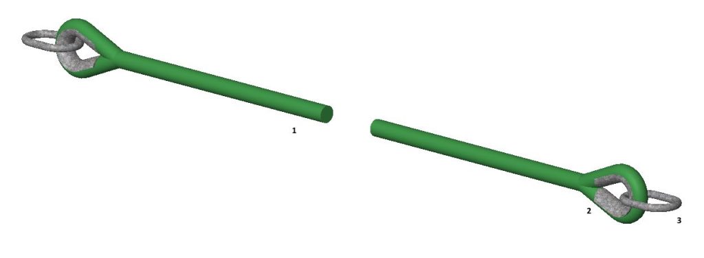
The grid rope consists of the following components:
- Rope
- Thimble
- Master link (Optional)
1.6 Bridle
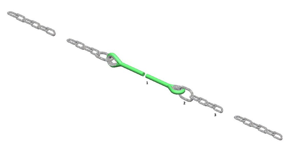
The connection between the grid and the pen is called a bridle.
Bridles can consists of the following components:
- Rope (1)
- Master link (2)
- Long-linked alloy chain (3)
- Master link can be welded to the alloy chain (Chain sling) or be connected using a shackle.
- Bridles runs directly from connection point to the pens as a 2 or 3-part.
2 Description of the components
2.1 Definitions
| Term | Definition |
|---|---|
| Analysis | Calculation of loads in a construction. |
| Seizing | A series of knots. |
| User manual | Document describing the correct identification of parts, transport, storage, handling, assembly, interface, operation, and limitations of main components in the fish farm. |
| Wave height | Vertical distance between a wave crest and the previous wave trough. |
| Wave period | The time a wave takes to achieve a single wavelength, defined between two zero-upcrossings of the mean water level (MW). – NOTE The wave period corresponds to the time it takes for two successive wave crests to pass through a fixed point. |
| Wave direction | The direction from which the waves are arriving. – NOTE Waves with directionality of 270° are arriving from the west. |
| Design service life | The expected time of use (service life) for a structure or its components, with an intended purpose and with assumed maintenance, without the need for extensive repair |
| Documented competence | Written proof that practical and theoretical skills have been met in relation to the requirements of an existing curriculum or training plan |
| Mooring | A system of lines and anchoringto keep the pen in the desired position. |
| Mooring line | Part of the mooring and includes grid ropes and bridles as well as a line to the anchoring. |
| Abrasion | Weakening of equipment strength as a result of cuts or friction. |
| Thimble | Insert to protect the rope loop. |
| Connection point (Mooring plate) | Component where grid ropes, anchor lines, bridles and buoys are attached. |
| Trip line | Rope attached at the rear of fluke anchors to raise and lower the anchor. |
| Unwanted incident | An event or condition that may cause harm to people, the environment or material assets |
2.2 Mooring components
Traceability information for all components can be found in Appendix 7. Inspection and maintenance of all components of the mooring system can be found in Appendix 1 through 5. How to measure wear for steel components is shown in chapter 7.10.1. Modifications and alterations are not permitted at product certified mooring components.
2.2.1 Anchoring
2.2.1.1 Plough anchor
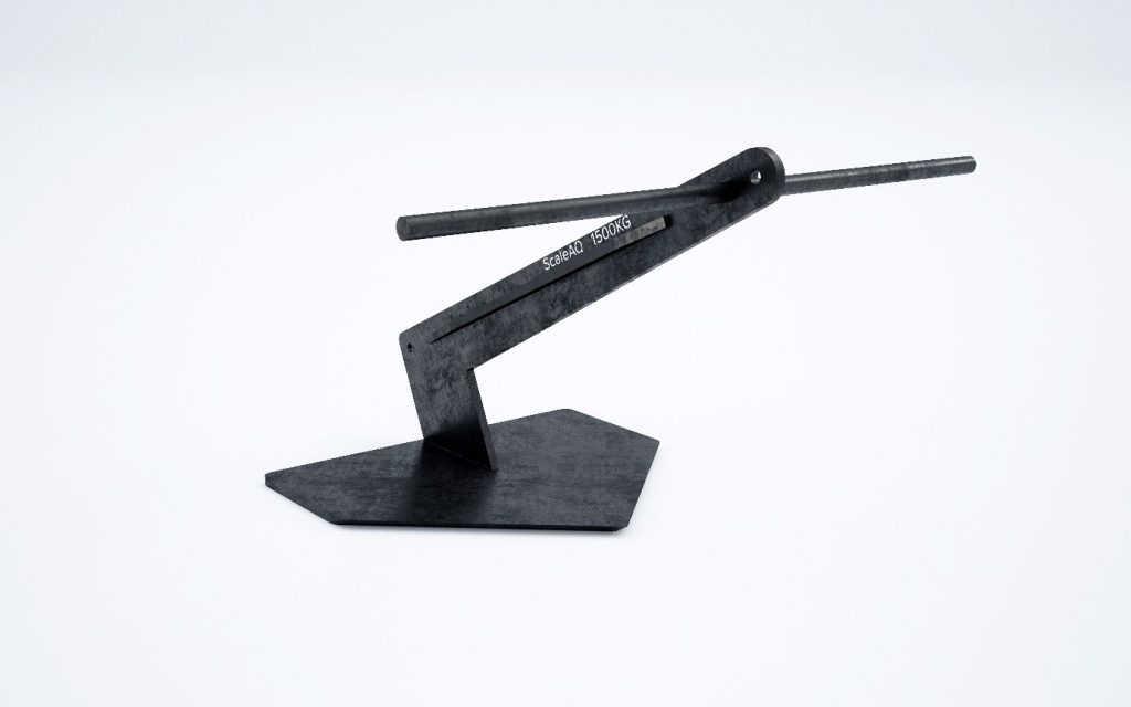
ScaleAQ Plough Anchor is designed primarily for sea bed with sand
- ScaleAQ Plough Anchor
- Capacity and minimum breaking load (MBL) are stated in the product certificate.
- Estimated service life: 20 years
- Wear limit: 10%
- The permitted lateral angle for shank load is 10 degrees. ScaleAQ must be contacted for assessment of a greater angle
| Item no. | Description | Weight [kg] |
|---|---|---|
| 300369 | ScaleAQ Plough Anchor | 700 |
| 300372 | ScaleAQ Plough Anchor | 1000 |
| 300377 | ScaleAQ Plough Anchor | 1500 |
| 300380 | ScaleAQ Plough Anchor | 2000 |
| 300385 | ScaleAQ Plough Anchor | 3000 |
2.2.1.2 Soft Hold anchor
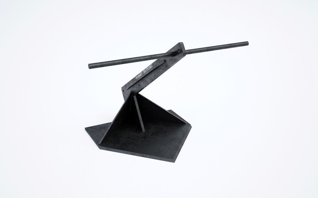
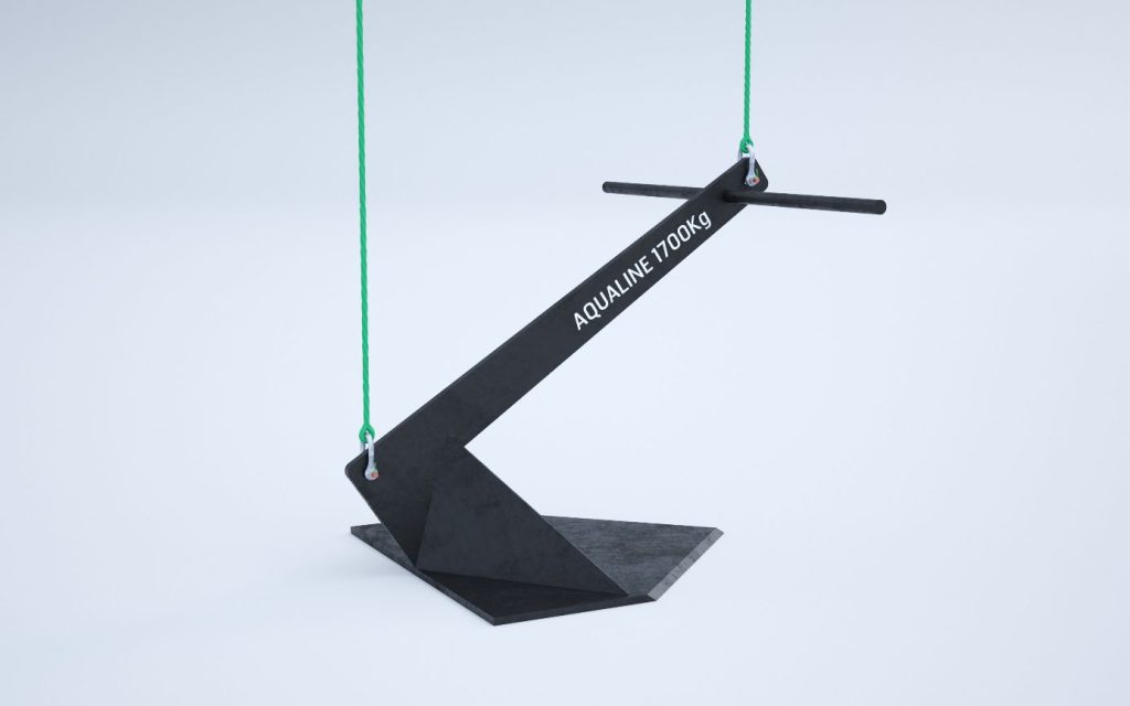
ScaleAQ Soft Hold Anchor is designed primarily for a soft seabed.
- ScaleAQ Soft Hold Anchor
- Capacity and minimum breaking load (MBL) are stated in the product certificate.
- Estimated service life: 20 years
- Wear limit: 10%
- The permitted lateral angle for shank load is 10 degrees. ScaleAQ must be contacted for assessment of a greater angle
| Item no. | Description | Weight [kg] |
|---|---|---|
| 302108 | ScaleAQ Soft Hold Anchor | 1700 |
2.2.1.3 Rock bolt
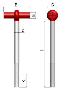
The rock bolts are made of high tensile and hot galvanized high-quality steel. ScaleAQ use bolts for grouting, either eye bolt, T-bolt or swivel bolt. Before installation, the holding power to the bottom bracket shall be documented through physical testing og minimum 50% of dimensioning load.
Rock bolts requires solid bedrock.
Estimated service life: 15 years
Wear limit: 10%
| Item no. | Description | D [mm] | L [mm] | MBL [tons] | G [mm] | E [mm] | K [mm] | B [mm] |
|---|---|---|---|---|---|---|---|---|
| 301295 | Rock bolt – Eye Bolt – Combi | 32 | 400 | 40 | 72 | 38 | 100 | – |
| 301296 | Rock bolt – Eye Bolt – Combi | 38 | 500 | 60 | 84 | 46 | 100 | – |
| 301297 | Rock bolt – Eye Bolt – Combi | 45 | 600 | 80 | 105 | 54 | 100 | – |
| 301293 | Rock bolt – T-bolt | 21 | 400 | 40 | 72 | 35 | 100 | 300 |
| 301294 | Rock bolt – T-bolt | 35 | 400 | 50 | 76 | 38 | 100 | 300 |
| 301370 | Rock bolt – T-bolt | 38 | 500 | 60 | 84 | 42 | 100 | 350 |
| 300440 | Rock bolt – T-bolt | 45 | 500 | 80 | 105 | 45 | 100 | 400 |
| 301733 | Rock bolt – T-bolt | 50 | 500 | 100 | 110 | 50 | – | 400 |
| 303586 | Rock bolt – T-bolt | 56 | 800 | 130 | 127 | 50 | – | 400 |
| 302818 | Rock bolt – T-bolt | 65 | 800 | 170 | 140 | 58 | – | 400 |
| 303613 | Rock bolt with Swivel | 45 | 500 | 80 | – | – | – | – |
| 303614 | Rock bolt with Swivel | 50 | 500 | 100 | – | – | – | – |
| 302884 | Rock bolt with Swivel | 57 | 710 | 140 | – | – | – | – |
2.2.2 Ground chain
ScaleAQ delivers ground chains in the quality K2. The chain is normally delivered in shots (27.5 meters). Other lengths can be produced upon request. Studless chains are used.
- Estimated service life: 15 years (see analysis for estimated fatigue life)
- Wear limit: 10%
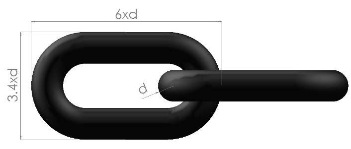
| Item no. | Description | MBL [tons] | D [mm] |
|---|---|---|---|
| 300344 | Studless chain 30mm | 47.6 | 30 |
| 300346 | Studless chain 36mm | 68.5 | 36 |
| 301737 | Studless chain 40mm | 84.5 | 40 |
| 302123 | Studless chain 48mm | 121.9 | 48 |
2.2.3 Rope – Polypropylen
ScaleAQ use 3-strand and 8-braided ropes in mooring systems. The rope is produced of polypropylene with the following properties:
- Very good durability
- Strong UV protection
- Floats
- Rot resistant
- Adapted for splicing and for use in mooring
Estimated service life:
- Rope in anchoring lines and grid lines: 15 years
- Rope in bridles: 10 years
| Item no. | Description | Construction | MBL [tons] |
|---|---|---|---|
| 300334 | Rope ScaleAQ 40mm | 3-strand | 25.7 |
| 300335 | Rope ScaleAQ 48mm | 3-strand | 36.6 |
| 300336 | Rope ScaleAQ 56mm | 3-strand | 48.7 |
| 300942 | Rope ScaleAQ 64mm | 3-strand | 62.5 |
| 300338 | Rope ScaleAQ 64mm | 8-braided | 68.2 |
| 301263 | Rope ScaleAQ Super Tech 48mm | 3-strand | 42.5 |
| 301264 | Rope ScaleAQ Super Tech 56mm | 3-strand | 55.4 |
| 301268 | Rope ScaleAQ Super Tech 64mm | 8-braided | 83.9 |
| 301379 | Rope ScaleAQ Super Tech 72mm | 8-braided | 105.5 |
| 301380 | Rope ScaleAQ Super Tech 80mm | 8-braided | 129.9 |
| 301309 | Rope ScaleAQ Super Tech 90mm | 8-braided | 164.0 |
| 302652 | Rope ScaleAQ 64mm, 5 tons* | 8-braided | 68.2 |
| 302653 | Rope ScaleAQ Super Tech 64mm, 5 tons* | 8-braided | 83.9 |
| 302654 | Rope ScaleAQ Super Tech 72mm, 5 tons* | 8-braided | 105.5 |
| 302655 | Rope ScaleAQ Super Tech 80mm, 5 tons* | 8-braided | 129.9 |
2.2.4 Rope – Sinking rope
ScaleAQ use 3-strand sinker ropes in mooring systems. The rope is produced from a mixture of polyester and polyolefin with the following properties:
- Very good durability
- Strong UV protection
- Sinks
- Rot resistant
- Adapted for splicing and for use in mooring
Estimated service life:
- Rope in anchoring lines and grid lines: 15 years
- Rope in bridles: 10 years
| Item no. | Description | Construction | MBL [tons] |
|---|---|---|---|
| 302232 | ScaleAQ sinking rope, white, 48mm | 3-strand | 47.0 |
| 302177 | ScaleAQ sinking rope, white, 56mm | 3-strand | 64.5 |
| 302349 | ScaleAQ sinking rope, white, 64mm | 3-strand | 94.0 |
| 302447 | ScaleAQ sinking rope, white, 72mm | 3-strand | 118.0 |
2.2.5 Master link and rings
In the connection between rope and other components, it may be necessary to maintain a certain distance to avoid unwanted abrasion or damage. This can be done by using an mooring shackle with hot-dip galvanized master link as an intermediate piece.
Rings can be used as a connection point, for instance, connecting weights to anchoring lines.
Estimated service life: 15 years
Wear limit: 10%
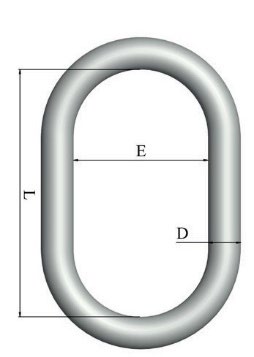
| Item no. | Description | MBL [tons] | D [mm] | E [mm] | L [mm] |
|---|---|---|---|---|---|
| 300450 | Master link galvanized Ø28mm | 60 | 28 | 110 | 190 |
| 301004 | Master link galvanized Ø34mm | 80 | 34 | 140 | 240 |
| 302106 | Master link galvanized Ø40mm | 120 | 40 | 150 | 250 |
| 300426 | Ring 32.O.6, galvanized | 68 | 32 | 225 | – |
| 300431 | Ring 38.O.6, galvanized | 112 | 38 | 225 | – |
| 300438 | Ring 45.O.6, galvanized | 153 | 45 | 265 | – |
2.2.6 Shackle
The following shackles are used in the mooring system:
- Mooring shackle
- Shackle specially developed for aquaculture
- Manufactured in high tensile and hot-dip galvanized alloy steel
- Estimated service life: 15 years
- Wear limit: 10%
Various applications can be used for securing option, see the following pages. The pictures show the recommended assembly method.
Loctite is considered a good securing option, based on user experience. It is always recommended to use Loctite on the shackle towards the anchoring plate and up against the buoy. This minimizes the risk of the shackle unscrewing itself.
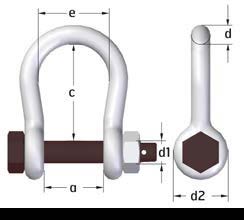
| Item no. | Description | MBL [tons] | e [mm] | a [mm] | c [mm] | d [mm] | d2 [mm] | d1 [mm] |
|---|---|---|---|---|---|---|---|---|
| 300393 | Shackle 28T | 28 | 58 | 44 | 100 | 19 | 47 | 22 |
| 300394 | Shackle 40T | 40 | 68 | 52 | 125 | 22 | 50 | 25 |
| 300399 | Shackle 60T | 60 | 89 | 62 | 150 | 28 | 58 | 28 |
| 300402 | Shackle 90T | 90 | 98 | 82 | 170 | 32 | 72 | 32 |
| 301813 | Shackle 110T | 110 | 150 | 112 | 200 | 42 | 94.5 | 45 |
| 301107 | Shackle 150T | 150 | 140 | 126 | 248 | 50 | 105 | 50 |
Plastic clips
Yellow: 28T to 40T
Green: 60T to 90T
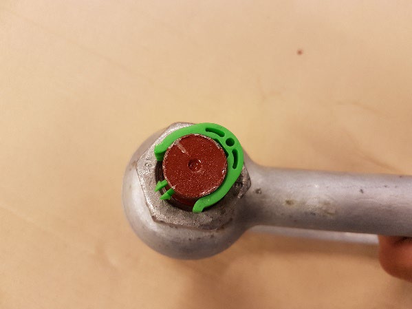
Stainless steel cotter pin (A4, DIN94)
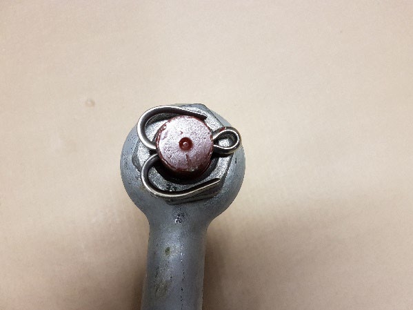
Make sure to use suitable pliers to bend the split pin and to start bending the longest split on the split pin. Suitable pliers may be waterpump pliers/small pipe wrench.
Plastic covered copper wire
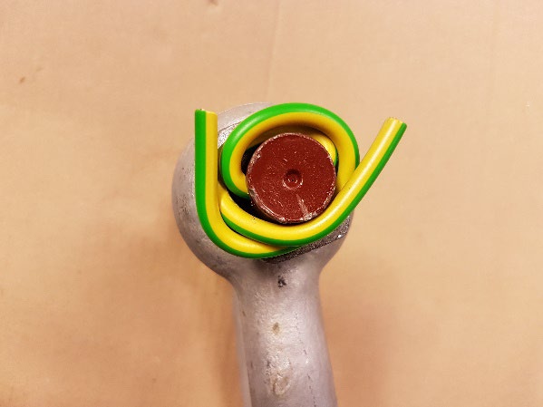
Bend it as tightly as possible around the bolt of the shackle/threaded section and avoid breaking the plastic guard of the splinter, which allows the copper to come into contact with the steel of the shackle.
Plastic covered steel wire
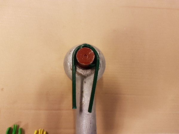
Bend it as tightly as possible around the bolt/threaded section of the shackle and avoid breaking the plastic guard on the splinter.
Loctite
Assembly
For best results, clean all surfaces (external and internal) with Loctite super cleaner (Item no. 300782) and let it dry. If the material is an inactive metal or the curing rate is too low, spray all threads with an activator (Item no. 300781) and let it dry. Shake the product well before use. To prevent the product from clogging the nozzle, make sure to prevent the tip from touching the metal surfaces during application. In the case of through holes, apply drops of the product to the bolt where the nut is to be attached. In the case of blind holes, drops of the product must be applied along the internal threads to the bottom of the hole. Assemble and tighten as needed. In the case of seals, a 360° wire is applied to the second foremost external thread, and not on the first thread. Force the material into the threads to fill the cavities. For larger threads and cavities, the product quantity must be adjusted accordingly, and a 360° string is also applied to the internal threads.
Disassembly
Dismantle using standard hand tools. In rare cases where hand tools do not work, due to extra-long overlap or because a very strong product was used, the nut or bolt should be heated to approximately 250°C. Dismantle while still hot.
| Item no. | Description |
|---|---|
| 300780 | Loctite 278 threadlocking |
| 302565 | Loctite 243 threadlocking |
| 300781 | Loctite activator |
| 300782 | Loctite Super Clean |
2.2.7 Thimble
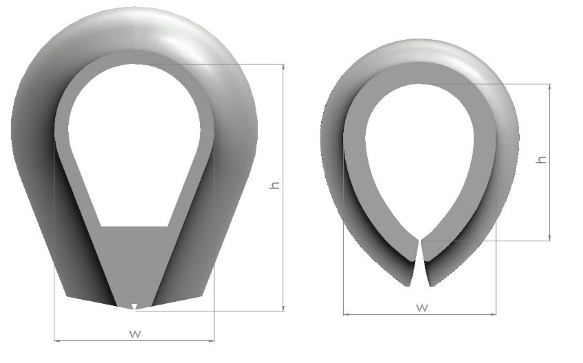
Thimbles are used in eye splice for the rope to prevent chafing and damage, and to maintain the rope breaking strength in the splice. ScaleAQ supplies hot galvanized thimbles in the mooring systems:
- Thimble – K3, K3-B, Tube and BS 464
- Estimated service life
- Thimble in anchoring lines and grid lines: 15 years
- Thimble in bridles: 10 years
Wear limit – 10%
- Estimated service life
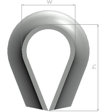
| Item no. | Description | w [mm] | h [mm] |
|---|---|---|---|
| 301508 | K3 Thimble 40mm | 65 | 100 |
| 301375 | K3 Thimble 48mm | 75 | 130 |
| 301066 | K3 Thimble 56mm | 85 | 142 |
| 301116 | K3 Thimble 64mm | 105 | 165 |
| 301149 | K3 Thimble 72mm | 110 | 200 |
| 301161 | K3 Thimble 80mm | 120 | 205 |
| 301285 | K3 Thimble 90mm | 150 | 247 |
| Item no. | Description | w [mm] | h [mm] |
|---|---|---|---|
| 301697 | K3-B Thimble 48mm | 75 | 130 |
| 301687 | K3-B Thimble 56mm | 85 | 142 |
| 301670 | K3-B Thimble 64mm | 105 | 165 |
| 131671 | K3-B Thimble 72mm | 110 | 200 |
| 131672 | K3-B Thimble 80mm | 120 | 205 |
| Item no. | Description |
|---|---|
| 300421 | Thimble HDG Tube 40mm |
| 301783 | Thimble HDG Tube 48mm |
| 300423 | Thimble HDG Tube 56mm |
| 300424 | Thimble HDG Tube 64mm |
| 301710 | Thimble HDG Tube 72mm |
| 301745 | Thimble HDG Tube 80mm |
| Item no. | Description |
|---|---|
| 300412 | Thimble BS464 40mm |
| 300413 | Thimble BS464 48mm |
| 300414 | Thimble BS464 56mm |
| 300415 | Thimble BS464 64mm |
| 300416 | Thimble BS464 72mm |
| 300419 | Thimble BS464 80mm |
2.2.8 Mooring plate
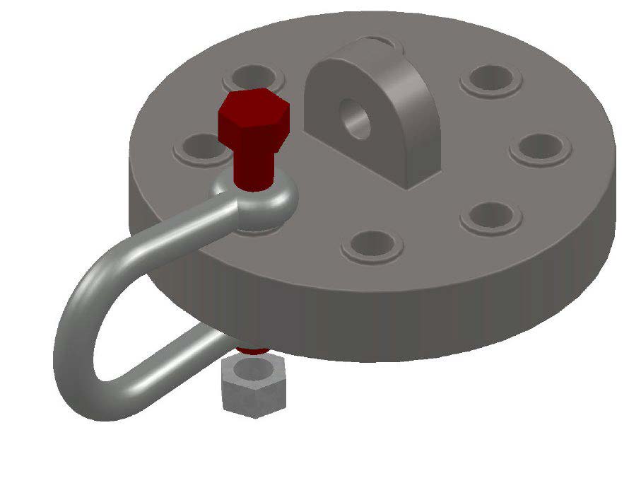
The mooring system provided by ScaleAQ includes a hot galvanized mooring plate. Anchoring lines, grid ropes, bridles and buoy rope/chain are connected to this mooring plate using mooring shackles.
ScaleAQ supply the following standard size for mooring plates:
- 40mm with 8, 12, 16 and 20 holes
- 70mm with 8, 12 and 16 holes
- Estimated service life: 20 years
- Wear limit for lifting hole: 30%
- Wear limit for mooring hole: 10%
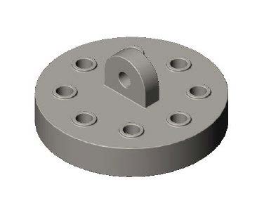
| Item no. | Description | Thickness [mm] | Diameter [mm] | Weight [kg] | MBL [tons] | MBL, lifting ear [tons] |
|---|---|---|---|---|---|---|
| 301383 | Mooring plate ScaleAQ 8 holes | 40 | 386 | 38 | 110 | 41 |
| 301384 | Mooring plate ScaleAQ 12 holes | 40 | 510 | 65 | 110 | 41 |
| 301385 | Mooring plate ScaleAQ 16 holes | 40 | 780 | 135 | 110 | 41 |
| 302828 | Mooring plate ScaleAQ 20 holes | 40 | 935 | 210 | 110 | 41 |
| 300444 | Mooring plate ScaleAQ 8 holes | 70 | 386 | 65 | 150 | 41 |
| 300445 | Mooring plate ScaleAQ 12 holes | 70 | 510 | 115 | 150 | 41 |
| 300959 | Mooring plate ScaleAQ 16 holes | 70 | 750 | 240 | 150 | 41 |
2.2.9 Long-linked alloy chain
A mooring system supplied by ScaleAQ can include long-linked alloy chains. Especially in bridles and as a buoy chain. Long-linked alloy chains can also be used for anchoring lines and grid rope. ScaleAQ supplies alloy chains by the following standard specifications:
- 16mm (Estimated service life: 5 years)
- 19mm – 25mm
(Estimated service life: 10 years when used in bridles, 15 years in grid ropes and anchoring lines) - See accredited mooring analysis for the estimated fatigue life
Wear limit: 10%
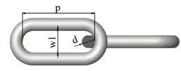
| Item no. | Description | MBL [tons] | d [mm] | p [mm] | w1 [mm] |
|---|---|---|---|---|---|
| 300321 | Chain LL alloy 16mm | 24.7 | 16 | 100 | 28 |
| 300348 | Chain LL alloy 19mm | 34.8 | 19 | 100 | 28 |
| 300349 | Chain LL alloy 22mm | 46.6 | 22 | 120 | 36 |
| 300965 | Chain LL alloy 25mm | 61.4 | 25 | 140 | 41 |
2.2.10 Chain sling with welded master link
Long-linked alloy chain with a master link in one end. Used in bridles and/or as a forerunner in anchoring lines.
Service life limitations and wear limits are the same as long-linked alloy chain, see section 3.7.
The lengths that are in stock are 2, 4 meters, 8 meters, 10 meters, and 15 meters. Other lengths by request.

| Item no. | Description | MBL [tons] |
|---|---|---|
| 302255 | Chain sling 19mm w/28mm master link, 2 mtr | 37.0 |
| 302580 | Chain sling 22mm w/32mm master link, 2 mtr | 49.6 |
| 301485 | Chain sling 19mm w/28mm master link, 4 mtr | 37.0 |
| 302024 | Chain sling 22mm w/32mm master link, 4 mtr | 49.6 |
| 301487 | Chain sling 25mm w/34mm master link, 4 mtr | 61.4 |
| 302262 | Chain sling 19mm w/32mm master link, 8 mtr | 37.0 |
| 302026 | Chain sling 22mm w/32mm master link, 8 mtr | 49.6 |
| 301871 | Chain sling 19mm w/28mm master link, 10 mtr | 34.8 |
| 302025 | Chain sling 22mm w/34mm master link, 10 mtr | 46.6 |
| 301489 | Chain sling 25mm w/34mm master link, 10 mtr | 61.4 |
| 302171 | Chain sling 19mm w/34mm master link, 15 mtr | 34.8 |
| 302098 | Chain sling 22mm w/32mm master link, 15 mtr | 49.6 |
2.2.11 Triangle mooring plate
Mooring systems supplied by ScaleAQ may include product certified triangular mooring plates. See user manual from manufacturer.
This component may be used when mounting weights or buoys on the anchoring line.
2.2.12 Mooring buoy
The anchoring system provided by ScaleAQ is delivered with product certified mooring buoys. See user manual from manufacturer.
2.2.13 Trip line
ScaleAQ anchors should be installed using trip line. This is made of rope with thimbles and fastened to the anchor with a shackle.
2.2.14 Floats
A float can be used to mark the position of the lift rope. There are no specific requirements for this. Estimated service life 5 years.
2.2.15 Trawl floats
In order to avoid contact and damage on the ropes from the seabed, trawl floats are placed in the connection between anchor chain and rope. Normally, 3 x 11” trawl floats are supplied for each anchoring line in the ScaleAQ mooring system. These can withstand submersion to 600m and have an estimated service life of 5 years.
3 Interaction with other components
3.1 Mooring of plastic pens
The bridles are connected to the plastic pen when the pen is placed in the grid. All bridles on one plastic pen must be the same type. The floater should be as centered as possible in the grid and all bridles must have the same pretension. The fastening of bridles to the floater depends on the type of floater used. The fastening of the bridles must be adapted as described in the plastic pen user manual and the capacity of the mooring points must be documented in the plastiv pen user manual or product certificate.
The maximum forces in the bridles are calculated in the mooring analysis. This analysis takes into account the net used in the plastic pen and any secondary equipment attached. The dimensional load must not exceed the maximum permissible load specified for the plastic pen in question.
3.2 Mooring of steel pens / barges
Anchoring lines are connected to the steel pens or barges according to specifications stated in the user manual for relevant steel pen or barge. The mooring analysis indicates the maximum load applied to the mooring point from the anchoring lines to the steel pen or barge. These defined loads must not exceed the maximum permissible loads specified in the product certificate for the steel pen or barge in question. It must be clearly stated in the user manual how to connect the mooring.
3.3 Boats and small barges
- Any use of boats/barges weighing less than 50 tons should be carried out without risk of damage to the mooring, floater, or net.
- Feed barges should be moored separately in their own mooring, or the mooring system has a mooring analysis that approves mooring of feed barges in it.
3.4 Maximum allowed loads from other components
The maximum permissible loads from other components shall be taken into account in the site-specific analysis that defines all requirements for mooring components. No loads beyond what is stated as requirements in the mooring analysis are permitted.
4 Assembling
4.1 Personnel requirements
Installation and assembly shall be carried out by personnel with at least 2 years of experience installing and operating mooring systems.
4.2 Customer responsibilities when assembling and installing on premises.
According to a signed agreement, the customer shall provide space for assembly; the necessary area is stated in the agreement.
Before the mooring is installed at the customer’s premises, assembly parts will arrive at on site before the installation itself. It is important that the parts are unloaded and stored in an appropriate and suitable area, so that no parts are damaged. Make sure that the area of assembly is not blocked by these parts. It is the customer’s responsibility to take care of the goods during the entire assembly period.
In the event that the unloading space is not at the assembly site, the customer is responsible for transporting the goods to the assembly site.
The customer shall use competent personnel, appropriate boats/machines, and other necessary equipment to ensure the correct assembly and installation of the mooring.
The customer is responsible for ensuring that all mooring components are assembled in accordance with the guidelines given in the product certificate and user manual.
For splicing of grid ropes, bridles and anchoring lines, a minimum of 5 tucks must be used on both 3-strand and 8-braided rope. When splicing the 8-braid rope, you may choose whether to use 2 strands or 1 strand.
For long splicing, two strands that are spliced together, a minimum of 5 tucks shall be used on the ropes that are spliced together. A total of 10 hitches.
4.3 Preparation for assembly and installation
The weather conditions must be such that the assembly and installation of the mooring do not affect health, safety, and the environment. Limitations on equipment release depend on the operating limitations of the installation vessel.
Components and equipment must be identified and checked for damage before assembly can begin.
Identify any boats/machines and other equipment necessary to assemble and install the mooring, as well as any precautions when using these. In order to install ground chains and anchor in a safe manner, a boat must be equipped with a crane with a lifting capacity that can handle the minimum weight of ground chain and anchor. A hoist must be present to handle the lift rope.
Only certified lifting equipment shall be used for the installation.
Make sure that the assembly area is cleared. Space requirements will depend on each individual mooring system. All mooring components are delivered tied together and gathered on pallets to minimize space requirements.
4.4 Assembly on the premises
The assembly of a complete mooring system will depend on the site and the mooring system.
4.4.1 Overview of components
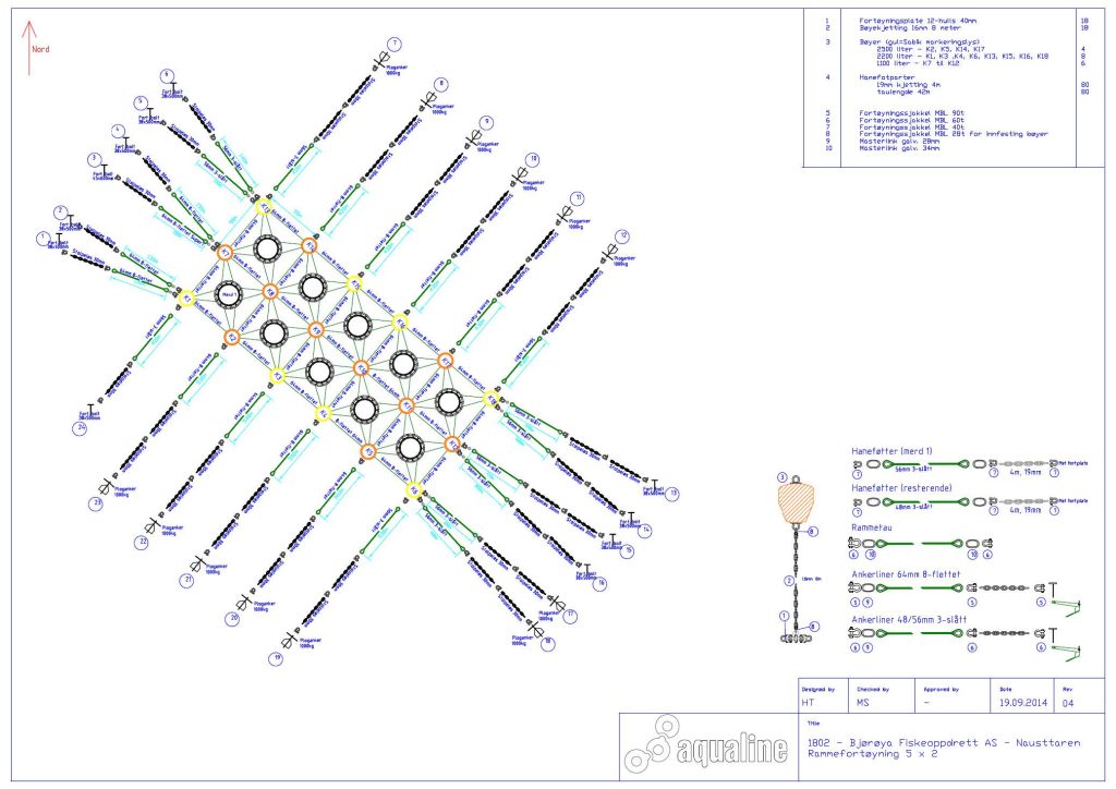
An overview of components is supplied in the form of order confirmation and drawings.
4.4.2 Installation – Step by step
The installation of the mooring system will depend on the site. The following procedure may be used as general instructions:
Step 1
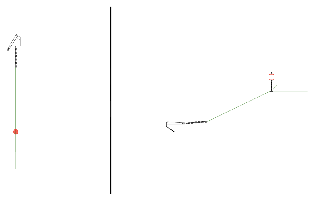
The first anchor is connected to an ground chain with a shackle. The other end of the ground chain is connected to the anchoring line using shackles. The shackle bolts are secured with nuts and securing option. The anchor is lowered using a trip line to ensure good positioning. See figure on the next page for the recommended handling of the anchor. Stretch out the anchor line and tighten with the help of a boat/barge so that the anchor digs down in the sea bed.
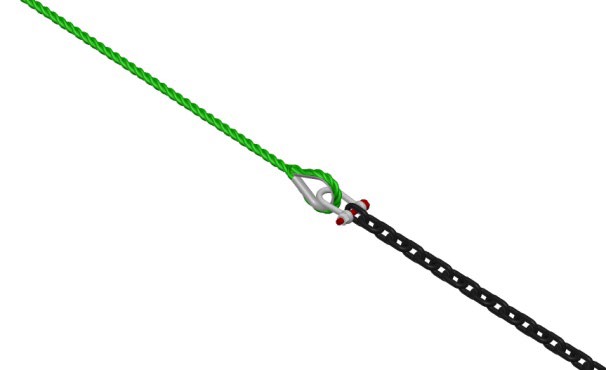
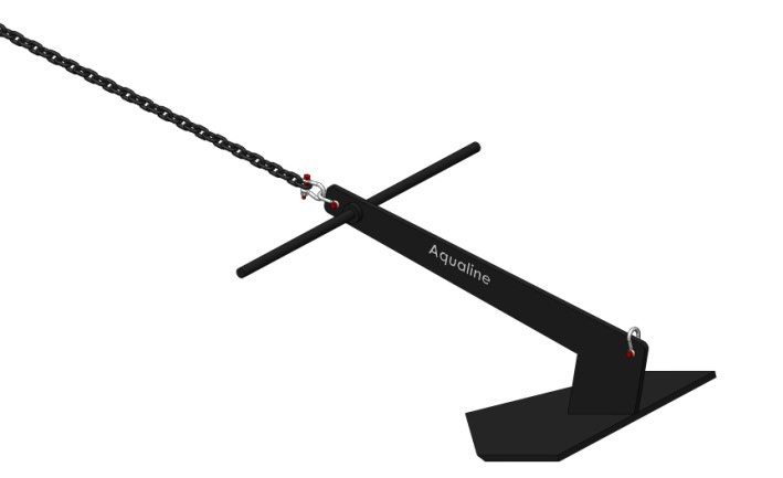
Once the anchor is set, fasten the other end of the anchor line to the connection point (mooring plate) in the first corner of the grid. At the connection point, the buoy chain and buoy are connected. Install the first grid rope lengthwise and crosswise.
Step 2
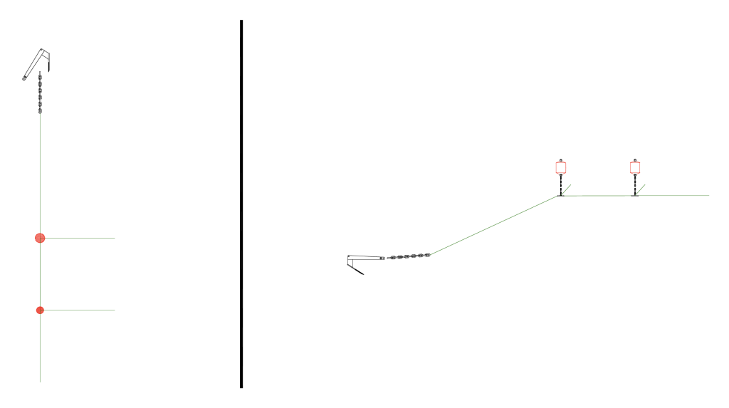
At the other end of the first grid rope, a new connection point with the buoy chain and buoy is connected. The next grid rope lengthwise and crosswise is connectes to the connection point. The same procedure is done for all grid ropes all the way to the corner of the grid.
Step 3
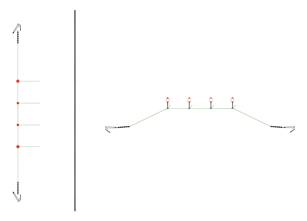
At the connection point in the opposite corner, connect the anchoring line, ground chain, and anchor in the same way as in step 1. The anchor is lowered using a lift rope to ensure good positioning. Stretch out the anchor line and tighten with the help of a boat/barge so that the anchor sits properly. After the anchor is set, the other end of the anchor line is fastened to the connection point (ring, plate, etc.).
Step 4
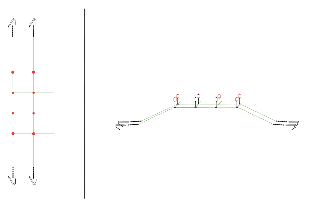
Start at the same end as in step 1. The anchor is set at the height of the first anchor, but with a side shift corresponding to the width of the grid. Continue as in steps 2 and 3, but also connect the grid ropes crosswise to the connection points from the first stretch.
Step 5
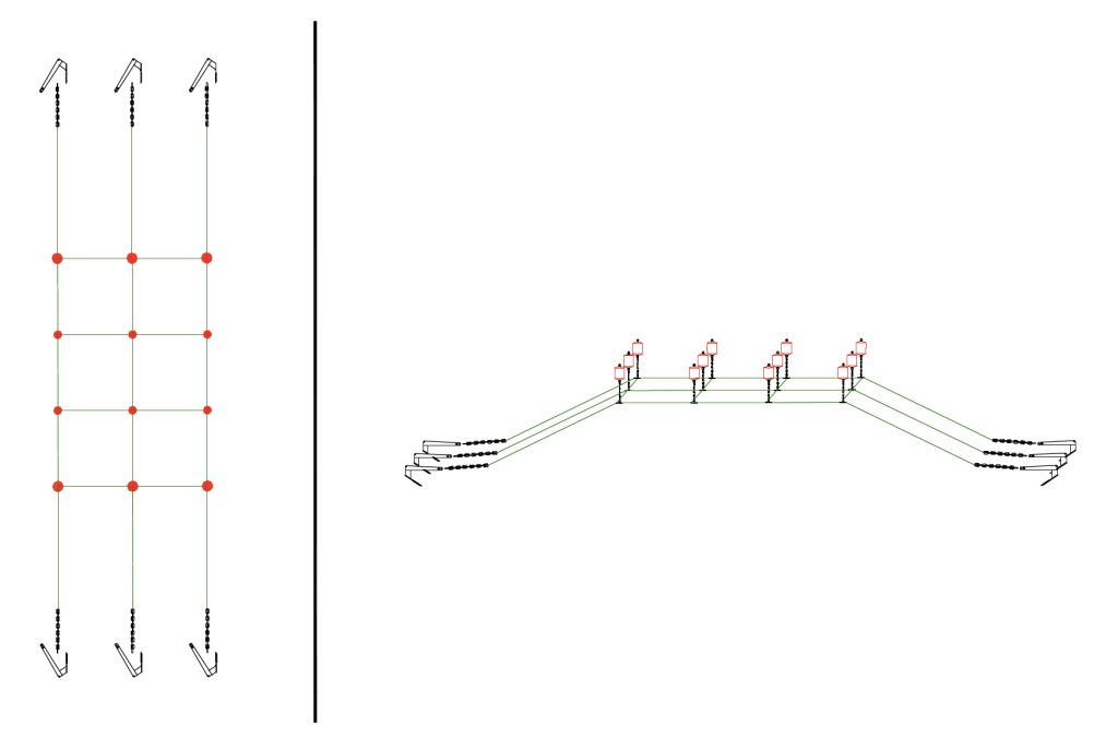
The last lengthwise stretch is laid out as in step 4.
Step 6
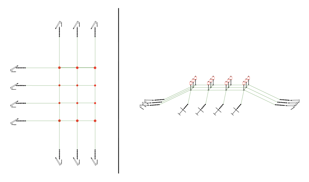
Connect anchoring lines along the long side.
Step 7
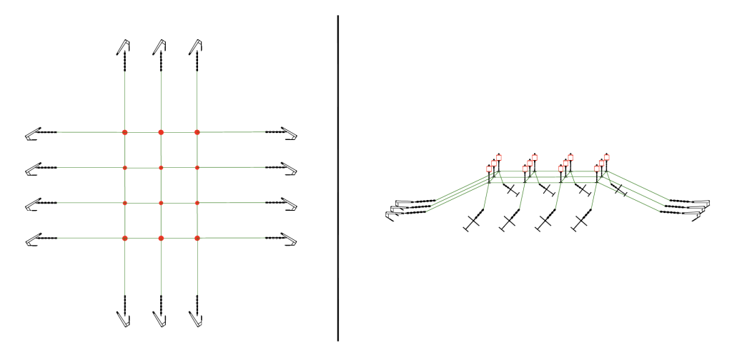
Connect anchoring lines along the long side opposite step 6.
Step 8
Alternatively, connect additional anchoring lines in the corners.
Step 9
The anchoring lines must be tightened so that all anchor lines have equal pretension. This can be checked by looking at the submersion of the buoys. Tighten so that the buoys are submerged to approx. 2/3 of their height. First, the anchoring lines are tightened lengthwise to the grid. Then tighten the side moorings and any anchoring lines at an angle in the corners. Make sure the lengthwise grid lines are straight. Check to see whether the buoys are aligned.
Step 10
Bridles are installed in relation to the installation of the pens in the mooring system. In order to secure the bridles in the mooring system, the connection points must be raised by crane or other suitable equipment on board the boat/barge. Install bridles in the desired grid where pens are to be placed.
4.4.3 Correct adjustment of bridles
Bridle lengths are calculated in relation to the grid size of the specific site. When installing new bridles in older rgids, accurate measurements of the grid prior to ordering bridles should be taken in order to correctly calculate the bridle lengths.
After fastening the pens to the grid with bridles, it is important to adjust these correctly so that they do not apply the wrong load (for tight bridles) or wear on the enclosure (for loose bridles).
When the pen is centered in the grid, the bridles must be adjusted so they are loose enough for the floater to move freely. Bridles should not be so loose that they get in contact with the net. This applies to all current conditions.
Chains are used at one or both ends of the bridles to adjust the length of the bridles.
Make sure that all bridles on the floater are adjusted equally when adjusting the bridle length.
Step 11
Attach the bridles to the mooring brackets on the pens once the pen is positioned in the grid. All bridles on a pen must be the same type.
Mooring shackle is used when the pen is connected to the mooring system.
When tightening the bridle, it is important to ensure that the pretension of the mooring grid is not transferred to the bridles.
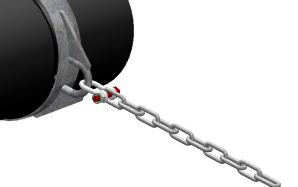
4.4.4 Rock bolt
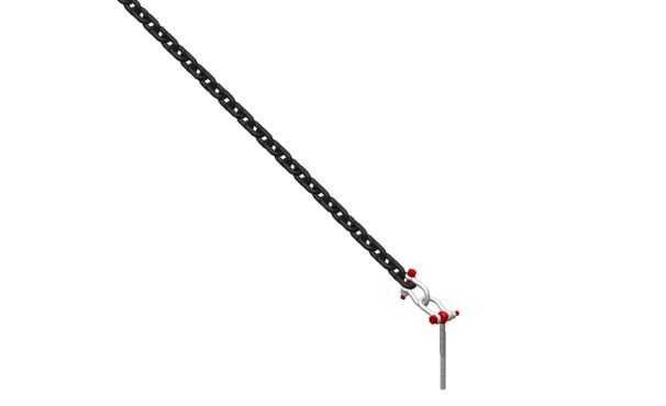
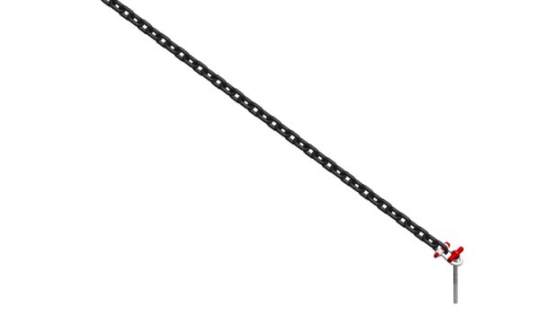
When using rock bolts, the same procedure applies as in chapter 4.4.2. The difference is that anchoring lines are attached to a rock bolt using a diver or ROV. The following procedure is recommended when installing rock bolts:
- The assigned position shall initially be used, but if there should be sea bed conditions that make it impossible to drill down at the designated coordinate, an assessment shall be made and the rock bolt is placed where the conditions permit based on topography/mountain strength.
- Prepare the rock bolt/shackle/chain and rope for marking buoy when vessel is securely anchored, and propeller disconnected.
- Chains and drilling equipment are lowered into the best possible position above the drilling site.
- Release drilling equipment and drill holes with a drilling depth that comply with the norm requirements for the bolt length in question, specified by red paint or tape, or spacer (swivel bolt). It is important that the shackle can move freely.
- When the hole is close to being finished, the diver gives the signal that the grouting should be mixed. The drill is hoisted, and the diver withdraws until it is confirmed that the machine is on board
- Then the bolt and the pre-mixed grouting mass (anchoring mass) are lowered to the diver. The anchoring mass is mixed according to the instructions in the accompanying user manual.
- The mass is pressed into the hole and the bolt is pressed into place to norm depth
- When using an eyebolt twist the bolt until it is aligned with the associated anchoring line.
- The chain and shackle are connected with bolt and securing option (recommended plastic covered steel wire) is inserted into shackle and bent so that the shackle nut cannot loosen.
- The chain is not to be touched until after the curing time has been met in accordance with the temperature listed in the user manual for the grouting mix (anchoring mass)
- The pinpoints coordinates are logged for documentation and the mooring line is tightened up against the connection point in the grid.
4.4.5 Final inspection of installation
Installation aids are removed carefully without damaging the mooring.
As an added security, ScaleAQ makes a final assessment of the mooring system. The customer submits an overview of how the mooring system was installed and, if applicable, which changes have been made compared to the planned system.
4.4.6 Landing the mooring
When removing the mooring system, do so in reverse order compared to the steps described in Chapter 5.2. You can lift the anchor using the trip line. Use a winch and crane for this task.
The required space for landing varies for each delivery. It must at least be enough space for the number of pallets/packages for the components that will be landed in that particular operation. In addition, there must be a clean area for disassembling the components. It is recommended that components such as rope, chain, and other hardware are packed on pallets. Anchor and chain can in some cases be packed loose and not on pallets where appropriate.
Area requirements:
- Pallet: Approx. 1 m2
- Anchor: Approx. 1,5 m2
- Buoy: Approx. 1,5 m2
Having an organized and cleared area for disassembling components is important. Here, it is important that enough space has been made available for the disassembly of the anchor and anchor line. The recommended area is a minimum of 6m2.
Most metal components in the mooring system are hot galvanized and do not have any specific storage requirements. Storing ropes made of synthetic fibers does not entail any major requirements. The rope is resistant to bacteria and mold and can be stored in a wet state. It is, however, important to protect it against direct sunlight and excessive heat. The best way to store the ropes is in a cold, dry, and well-ventilated environment. It is recommended to clean the components and rinse them in fresh water after use in order to hold up in storage as well as possible.
It is important to be aware of any damage after landing and storage, if the components are intended for reuse. After storage in accordance with set requirements, it is sufficient to inspect the components before reuse, with the exception of ropes. For ropes intended for reuse, tensile testing is carried out in addition to the inspection to check the residual capacity in comparison to the original product certificate. Experience shows that ropes that have been used at the sea surface are normally not suitable for reuse; this pertains to bridles and grid ropes.
5 Installation
Installation to other components must be done in accordance with the requirements of the other components’ user manuals and/or product certificates. There must be clear requirements for how other components should be installed to the mooring. Risk factors that are important to be aware of is ensuring that the capacity of other components is not exceeded, and that the fit of the fastening to the mooring from the fastening to other components is safeguarded and cannot impose wrong loads on other components or mooring that can lead to a reduction in capacity. See also chapter 4.4.3 for a description of the fastening to the pen.
6 Use
6. 1 General requirements
During operation, the mooring must not be subjected to loads that will impair its quality and service life. If conditions/situations should arise that cause strain/damage to the mooring, the affected elements/components must be checked and replaced if necessary. If a component needs to be replaced, it should be replaced with the same or equivalent type approved for this purpose.
Personnel responsible for the operation and maintenance of the mooring system must have at least 2 years of experience with mooring systems and experience with ropes and splicing. It will be specified if any operations require additional qualifications.
In the event of special physical environmental conditions, the personnel responsible for the operation of the mooring system must follow the guidelines as shown in chapter 7.6.
Prerequisites and limitations for the use of cranes and forklifts when handling the mooring system must be met in the form of statutory training within the relevant areas. It is the user’s responsibility to ensure that this is taken care of.
6.2 Modifications
All modifications to the mooring system must be approved by ScaleAQ . If modifications are made without approval, all liability by ScaleAQ will be forfeited.
A modification is defined as the mooring system no longer being in accordance with the mooring analysis as laid out.
6.3 Record-keeping
All maintenance, changes, modifications, expansions or similar for the mooring system must be logged and archived.
7 Inspection and maintenance
7.1 General requirements
During normal operation, periodic inspection and maintenance of the mooring system must be carried out.
During normal operation, periodic inspection and maintenance of the mooring system must be carried out.
Procedure ID 2899 – Risk assessment – ScaleAQ – Anchoring – periodic inspection of buoys
Procedure ID 2900 – Risk assessment – ScaleAQ – Anchoring (Planning, design, execution, delivery, installation, operation)
Procedure ID 2898 – Risk assessment – Inspection and maintenance anchoring
The procedures are registered in ScaleAQ’s document register, Landax. The risk assessments are carried out in accordance with NS 5814, requirements for risk assessments.
Inspection and maintenance that differs from the minimum requirements must be approved by ScaleAQ.
The personnel responsible for the inspection, maintenance and replacement of the mooring system must have at least 2 years of experience in the operation of mooring systems and experience with ropes and splicing. It will be specified if there are operations that require additional qualifications.
7.2 Laying out and mooring system
Requirements for installing and inspecting mooring systems are found in Section 23 of the Norwegian NYTEK Regulations.
ScaleAQ requires inspection that at a minimum includes the points in:
 Inspection after installation of the mooring system (Appendix 1).
7.3 Tensioning the mooring system when laying it out
When installing mooring systems for aquaculture facilities, it is important to ensure that all anchoring lines and grid ropes are tensioned with equal force, as far as possible. The timing of tensioning must be in accordance with the direction of the current. It is recommended that the tensioning is done with the current.
The first tensioning of the mooring system is recommended to be done before the pens are installed in the mooring system.
7.4 Retightening of the mooring system
It is recommended to retighten the mooring system within 3 to 6 months after the mooring system has been laid out. This is because the mooring system for floating aquaculture facilities consists of ropes that stretch under load. The loads distribute themselves unevenly in the floating aquaculture facility, leading to a difference in how much anchoring lines, grid ropes, and bridles stretch. Retightening should be done with approximately the same load as when the mooring system was installed.
7.5 Inspection intervals
ScaleAQ requires the following minimum inspection and maintenance intervals of the mooring system:
- Daily (see appendix 2)
- Monthly (see appendix 2)
- Within 3 – 6 months (see appendix 3)
- Within 30 months (see appendix 4)
- Within 60 months (see appendix 5)
- Within 90 months (see appendix 4)
Explanation of the method as specified in appendixes 1 to 5 and appendix 6:
GVI = General Visual Inspection
Example from daily inspection – check that all marker lights work.
CVI = Close Visual Inspection
Example from monthly inspection – check that the marker lights are not damaged.
DI = Dimension Inspection – measurement of wear on components
7.6 Inspections in the event of unforeseen events
ScaleAQ requires inspection of the mooring system if unforeseen events occur. This includes events such as:
- A vessel has hit the aquaculture facility
- Unusual weather situation
- An abnormal difference between high and low tide
- Vandalism
- Floating objects
Inspection before and after bad weather (see appendix 5)
Inspection if unforeseen events occur (see appendix 6)
7.7 Replacements
All replacements in the mooring system must be approved by ScaleAQ. If modifications are made without approval, all liability by ScaleAQ will be forfeited.
7.7 Record-keeping
All inspection and replacement of components/main parts of the mooring system shall be logged and archived. It is the responsibility of the customer to log all changes and results from inspections so that it is traceable and can be viewed throughout the service life of the mooring system.
7.9 Spare parts
Correct spare parts are identified and compared against data in product certificates and component lists for the relevant mooring system.
The following spare parts and quantity are recommended to be kept in an indoor storage facility on site for quick repairs.
- Shackle: 5% of the relevant dimension of shackle
- Thimble: 5% of the relevant dimension of thimble
- Rope: 110m for grid ropes
- Rope: Sufficient rope to replace one bridle
- Rope: Sufficient rope to replace the longest anchoring line
- Master link: 5% of the relevant dimension of master link used in the mooring
- Connection point: 1 pcs
- Buoy: 1 pcs of the largest buoy
- Marker light: 1 pcs
- Ground chain: 2 shots
- Anchor – 1 pcs. of the largest anchors
- Rock bolt – 1 pcs. of the largest bolt
7.10 Replacing components
7.10.1 Estimated service life
The estimated service life of chain and chain components, shackles, rock bolts, steel hardware for mooring buoys, thimbles, and anchors are based on criteria for wear and corrosion. Maximum wear/corrosion must not exceed the requirement specified for each component.
For example, a component where 10% wear of the material diameter is approved, measured over 2 diameters.
(D1 + D2) 90° offset relative to each other.
Meaning the remaining diameter ((D1 +D2) / 2) must be at least 90% of nominal diameter Dn.

Some sites may have an extremely corrosive environment and have extreme movements that can reduce the service life significantly. Therefore, it is important to follow the maintenance program for inspection and maintenance.
The service life of the rope is based on maintenance having been executed as recommended. We know from experience that synthetic ropes may have a longer service life than this, but this is provided that the rope is not subjected to damage/overload. With this in mind, great emphasis has been placed on inspection of ropes in our maintenance program.
When inspecting ropes in the mooring system, make sure to check that there are no breaks in the fiber and that the splice is intact. If there are visible breaks in rope fibers and/or the splicing is not intact, the rope must be discarded.
For anchors, the replacement criteria are similar to that of chain components.
7.10.2 Service life extension for components
The service life of the components included in the mooring system is listed under each component in Chapter 2.2 of this user manual.
When the service life of the component has expired, a service life extension of the mooring component itself or of the mooring system as a whole is possible.
Service life extension is done in accordance with Appendix F (normative) of NS 9415:2021.
7.10.3 Grid rope
If the complete grid rope or individual components of a grid rope are to be replaced, use the following procedure:
- Lift the connection point
- Secure the connection point in the boat to remove the tension in the grid rope to be replaced
- Disconnect the grid rope from connection point
- Connect the new grid rope to connection point
- Repeat the procedure for the other end of the grid rope
- Lower the connection point
- Check the pretension of the mooring system after the replacement is finished.
7.10.4 Anchoring line
If the whole anchoring line is to be replaced:
- Lift the anchor with trip line
- Reel the anchoring line towards the connection point
- Disconnect anchoring line from connection point
- Install new anchoring line
- Install anchor. Refer to step 1, Chapter 6.4.3
- Check the pretension of the mooring system after the replacement is finished.
7.10.5 Bridle
If a complete bridle or individual component in the bridle is to be replaced, use the following procedure:
- Disconnect the bridle from the pen
- Lift the connection point
- Disconnect the bridle from the connection point
- Connect new bridle to connection point
- Lower the connection point
- Connect the bridle to the pen
- Check the pretension of the bridles and the mooring system after the replacement is finished.
7.10.6 Connection point
If a connection point is to be replaced, use the following procedure:
- Lift the connection point
- Secure the grid ropes, bridles and any anchoring lines to the boat to remove the tension on the connection point to be replaced
- Disconnect the buoy, grid ropes, bridles and any anchoring lines from the connection point
- Connect the buoy, grid ropes, bridles and any anchoring lines to the new connection point
- Lower the connection point
- Check the pretension of the mooring system after the replacement is finished.
7.10.7 Buoy
Replacement of the buoy is done using the following procedure:
- Lift the connection point
- Open the shackle under the buoy and disconnect from the buoy
- Install the new buoy
- Lower the connection point
7.10.8 Anchor
Replacement of anchors is carried out using the following procedure:
- . Lift the anchor using trip line winch
- . Lift anchor onto deck using a crane
- . Replace anchor
- . Install the new anchor. Refer to step 1, Chapter 6.4.3
8. Transport and Storage
8.1 Handover
It is important to carry out an inspection when the mooring system and components are handed over to ensure that everything belonging to the mooring system is included in the delivery.
8.2 Packing for transport and storage
Mooring components and the complete mooring system are delivered from our warehouse and suppliers prepackaged and labeled for transport to the assembly site. Mooring components are supplied on pallets and packaged in plastic wherever appropriate in order to minimize space requirements. Most metal components in the mooring system are hot galvanized and do not have any specific requirements for transport or storage. It is important to ensure that no damage from contact with sharp edges or chafing occurs when packing ropes for transport. It is important to protect the rope from exposure to direct sunlight. When unwinding the rope for splicing grid ropes, bridles and anchoring lines, it is important to ensure that this is done in such a way that you do not get kink on the rope. The correct method is described in the splicing procedure in ScaleAQ AS’ quality system. This can be sent upon request.
There are no major requirements for storing synthetic fiber ropes. The rope is resistant to bacteria and mold and can be stored in a wet state. However, it is important to protect it against direct sunlight and excessive heat. The best way to store the ropes is in a cold, dry and well-ventilated environment.
8.3 Labeling during shipping
Pre-spliced grid ropes, bridles, and anchoring lines are wrapped with plastic and an A4-format label is placed in at least two different spots on the parcel. On the thimble end of each of these prefabricated components a plastic tag is attached. Thimbles are marked with a permanent marker.
8.4 Grid ropes
The grid ropes are coiled one by one and wrapped in plastic. Labels contain the following information:
- Location
- Grid rope
- Line length
- Dimension
- Batch no. rope
- Batch no. thimbles
- Batch no. master links
8.5 Bridles
The bridle lines are coiled one by one and wrapped in plastic. Labels contain the following information:
- Location
- Side part or middle part
- Dimension
- Length rope
- Batch no. rope
- Batch no. thimble
- Batch no. chain sling
- The thimble is marked with middle or side part, line length, dimension.
Three-part bridles are placed on one pallet. Two-part bridles are placed two or more parts on one pallet. The pallet is wrapped in plastic.
Labels must be placed in two different spots (inside the plastic) with the following information:
- Location
- Number of bridles on the pallet
- Dimension rope
8.6 Anchor lines
The anchor line is coiled and wrapped in plastic.
Labels contain the following information:
- Location
- Line number
- Line length
- Dimension
- Batch no. rope
- Batch no. spliced thimble
The thimble is marked with line numbers, line length, dimension.
8.7 Anchor chain/buoy chain/ bridle chain
Label attached with strips in one end link on the chain.
Labels contain the following information:
- Type of chain
- Location
- Dimension
- Batch
If the chains are packed on pallets, the pallet frames are marked with the type of chain, location, dimension, batch, and number of shots/number of lengths/number of running meters (depending on the type of chain).
8.8 T-bolts, anchoring shackles, Master links, Thimbles, trawl floats
Two pallet frames are marked with a label describing the type of product(s), dimension, and quantity
8.9 Unloading anchoring goods
Deliveries shall be checked upon receipt so that any defects or damages are noted on the delivery bill with a countersignature from the driver.
In general, the following points must be included in the inspection:
The delivery note is compared to the delivery address, the contents are checked against the number of parcels and any transport damage. Deviations/damages must be noted in the delivery note before signing and a copy must be given to the driver. Transport damage is documented with pictures.
When unloading, the freight carrier must be looked over to ensure it is complete and safe for unloading. If there is damage, the necessary precautions must be made before unloading.
Be careful, use suitable forklifts or cranes designed for the job and make sure to have your certificates and procedures in order. Suitable and approved equipment for unloading must be used, such as pallet forks, lifting yoke, approved lifting straps and so forth.
Be observant of your surroundings and have good procedures if there are several of you present. Be extra aware in case of bad weather and make sure that doors and so forth on the truck/container are well secured.
8.10 Space requirement
The space required for installation depends on each delivery. There must at least be enough space for the number of pallets/packages for the components to be used in that particular operation. In addition, there must be a clean area available for assembling the components. Components such as rope, chain, and other hardware are usually packed on pallets. Anchor and chain can in some cases be delivered loose and not on pallets where appropriate.
Area requirements:
- Pallet: Approx 1m2
- Anchor: Approx. 1.5m2
- Buoy: Approx. 1,5m2
Having an organized and clear area for assembling components is important. Here, it is important that space has been made so that the anchor and anchor line can be connected together and can be freely released into the sea when installing the anchor. The recommended area for this is a minimum of 6m2.
8.11 Disposal
All components of the mooring system can be recycled.
Buoys are sorted into different fractions (metal, PE and EPS). PE plastic is processed into plastic granules, EPS and metal are reused or recycled by external companies. The metal from the mooring system is reused or recycled by companies that handle this. All components of the mooring system are established in circular value chains.
9. Manufacturer and Product identification
9.1 Manufacturer
For more than 30 years, ScaleAQ AS has delivered mooring systems both in Norway and internationally. We perform mooring system analysis and supply product certified components for mooring. Product certification has certificate number PR032 from Aquastructures AS is available upon request.
ScaleAQ mooring system is designed and manufactured in accordance with NS 9415. The requirements for the mooring system are taken from the dimensioning values given in the site survey. The mooring system will be adjusted to the pens and the net as well as the barge, following specifications of the respective manufacturers of these primary components. ScaleAQ mooring system is dimensioned in accordance with mooring analysis carried out by either ScaleAQ AS (accredited with inspection number 036) or other suppliers.
The user manual describes important information on how the mooring system and components supplied by ScaleAQ are to be transported, handled, installed, inspected and maintained to maximize the utilization of properties and service life.
The form for inspection of mooring is attached as appendix to the user manual.
There is no special background knowledge needed for the reader, but should there be things that are poorly explained, feel free to contact us directly.
This manual is retroactive for all mooring systems laid out after 01.01.2012.
CONTACTS
| Position | Name | Mobile phone | |
|---|---|---|---|
| Project Manager Mooring | Øyvind Refsnes | oyvind.refsnes@scaleaq.com | +47 920 22 455 |
| Head of Mooring | Kasper Wåsjø | kasper.wasjo@scaleaq.com | +47 980 48 076 |
9.2 Product identification
The identification of the mooring system as a whole is shown in Chapter 1 in this user manual. Identification of individual parts with trademarks and type specifications is shown in Chapter 2 of this user manual.
10 Revision history
| Revision | Date | Changes |
|---|---|---|
| 1 | 27/06/2025 | First version. |
11 Reference list
Regulations on requirements for technical standards for aquaculture facilities for fish in sea, lake and rivers (NYTEK23) (FOR 2022-08-22-1484)
NS 9415:2021 – ‘floating aquaculture facilities, site survey, design, execution and use’
Risk analysis mooring, ScaleAQ (stored on Landax)