Manuals
Sinker tube system
Important information is marked with the following symbols:

1 Summary with an overview of the component and key points related to escape prevention
1.1 General definitions
| Aquaculture farm | Installation for the farming of fish. |
| Design working life | Assumed period for which a structure or part of it is to be used for its intended purpose with anticipated maintenance but without major repair being necessary. |
| Operation | Fish farming at site, including all installation and operation activities performed at the site while fish farming is in progress, and that are of relevance to the escape prevention of fish. |
| Extra equipment | Equipment that is not a main component. |
| Inspection | Systematic inspection/examination, usually visual, to ensure that the equipment satisfies the requirements. |
| Floater | Structure whose main function is to provide an enclosure with buoyancy and/or stiffness. |
| Anchoring system | System of lines and bottom attachments with the main function of keeping the aquaculture farm or raft in position. |
| Bridles | Anchoring line between the floater and the anchoring system. |
| Main component | Part of an aquaculture farm that holds one or more of the installation’s load bearing main functions. Example: Floater, anchoring system, raft and enclosure. |
| Enclosure | Net or other system of load bearing parts that form a barrier between the farming volume in a production unit and the surrounding water volume. |
| Bracket | Component keeping the inner and outer floating collar pipes together. |
| Weight | Weight or other device attached to the net to achieve the intended shape. Centre weight is attached beneath the bottom centre of the net-cone. |
| Cage | Floater with enclosure. |
| NS9415:2021 | Standard which sets out functional requirements for floating aquaculture farms and will be fundamental for stakeholders in the aquaculture industry, such as authorities, supervisory bodies, designers, suppliers, actors within R&D and manufacturers, as well as aquaculture farm owners. |
| NYTEK23-regulation | Governing Regulation for Fish Farming in Norway. |
| Product certificate | Document confirming that the net is produced in accordance with requirements in NYTEK23 and NS9415:2021. |
| Suspension system | Weight, sinker tube or similar used to keep the three-dimensional shape of the net. |
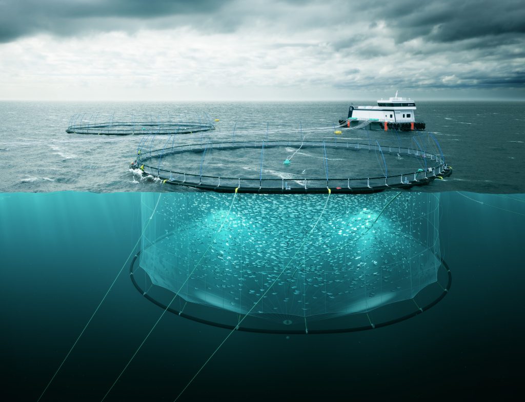
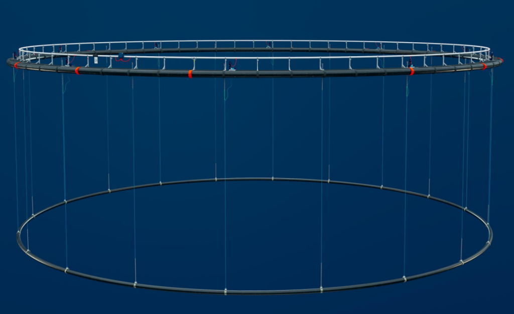
1.2 Introduction
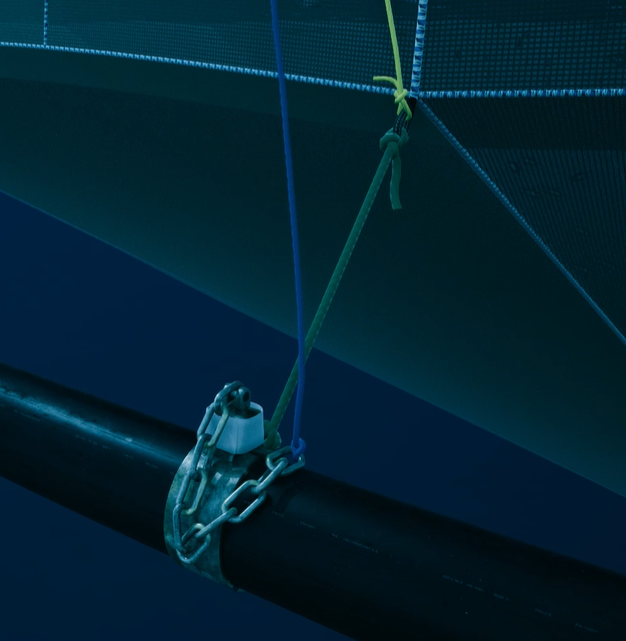
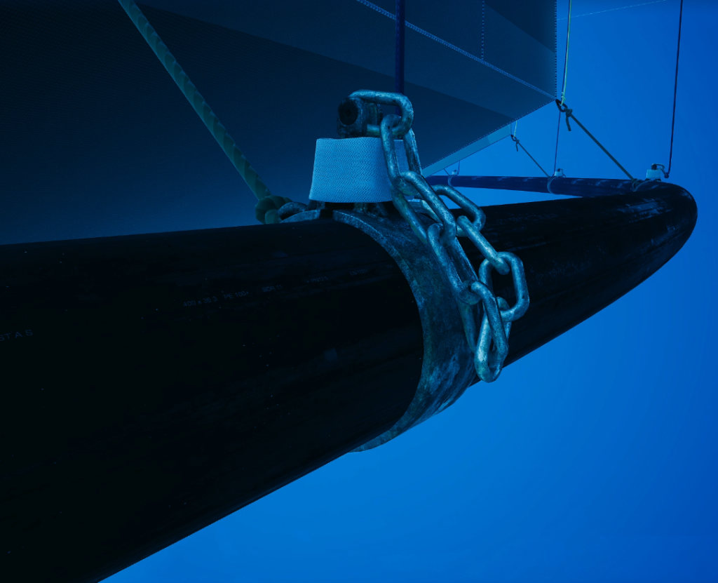
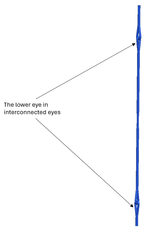
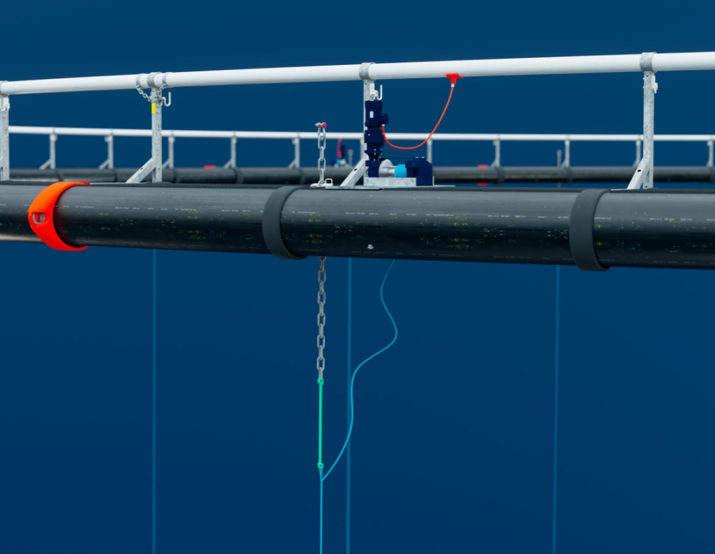
The sinker tube on the ScaleAQ FrøyaRingen pen is suspended in a dedicated suspension system, which may consist of chain, fiber rope, or a combination of both. Suspensions using fiber rope typically consist of a combination of chain at the top and one or more lengths of fiber rope spliced together with eye splices. In addition, there is a chain/loop at the lower end. The eye splices are designed for attaching the sinker tube at multiple levels. In some cases, the eye splices are interconnected so that one or more lengths of the suspension can be removed if the suspension is to be used for nets of different depths. Some suspensions are also delivered with round slings in the eye splices. These round slings must NOT be used to lift the sinker tube. They are ONLY intended for inserting a service pin.
2 Description of the sinker tube system and its components
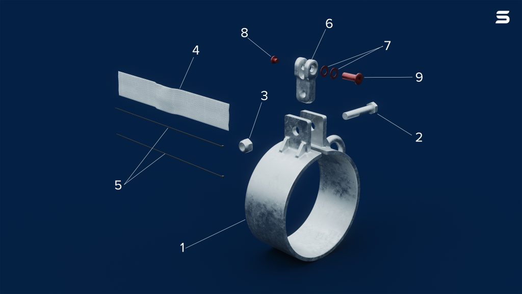
- Sinker tube bracket in galvanized steel.
- Bolt
- Nut
- Sinker tube cap
- Cable tie
- Sinker tube adapter
- Norlock lock washer
- Nut
- Bolt
2.1 Main principles of the sinker tube system
2.1.1 The net is attached to the sinker tube
2.1.2 The net is attached to a weight sliding along the suspension system
2.1.3 The net with waistrope connected to the suspension system with steel rings/loops
Check the user manual for the specific net regarding attachment of net to pen and suspension system.
2.2 Assumptions and limitations
It is a requirement that only equipment and components approved by ScaleAQ AS are used when replacing equipment and components on the ScaleAQ Sinker tube system.
ScaleAQ has responsibility only when spare parts and service personnel approved by ScaleAQ AS are used.
2.3 Undesired events
2.3.1 Chafing on the net
If contact between the net and the sinker tube suspension poses a risk of chafing, measures must be taken — such as selecting materials that resist abrasion, reinforcements, double securing, or other actions to prevent holes from forming during a standard operational cycle of the net.
2.3.2 Damage to sinker tube suspension
If one or more sinker tube suspensions become damaged or break, they must be replaced as soon as possible. This must be done in consultation with ScaleAQ.
2.3.3 Corrosion and material loss on sinker tube chain
If corrosion on the sinker tube chain makes the surface significantly rougher than a new chain, this may cause damage to the net in the event of contact. It is then recommended to replace parts or the entire chain. In cases of heavy corrosion, visible cracks/damage, or material loss in the chain, there is a risk of chain failure. In such cases, it is recommended to replace the entire chain.
See Chapter 7.3.1 for chain replacement criteria.
If the surface of the chain near the clamp is heavily corroded, it can be assumed that the chain is similarly corroded further down in the water.
2.3.4 Operation with a reduced number of sinker tube suspensions
The weight of the sinker tube must not be supported by fewer suspensions than those delivered by ScaleAQ for the specific pen and sinker tube system. The load must be evenly distributed across all suspensions.
2.3.5 Undesired events in biological production
Contact ScaleAQ for guidance on how such situations should be resolved.
3 Interaction with other components
3.1 Interaction with the pen
The sinker tube system delivered by ScaleAQ is designed to document compatibility with the relevant/permitted pen.
The product certificate for the pen contains important information about compatibility and usage limits for the sinker tube system in combination with the pen.
3.2 Interaction with the net
The sinker tube system delivered by ScaleAQ is designed to document compatibility with the relevant/permitted net.
The product certificate for the pen contains important information about compatibility and usage limits for the sinker tube system in combination with the net.
3.3 Interaction with permanent extra equipment
When using permanent extra equipment in the net that affects system integrity and response behavior, ScaleAQ must be contacted for advice and approval.
3.4 Interaction with temporary extra equipment
When using temporary extra equipment in the net that affects system integrity and response behavior, ScaleAQ must be contacted for advice and approval.
4 Installation of sinker tube
4.1 Installation on the pen
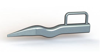
4.1.1 Service pins
There are two types of service pins that can be used, but they differ in how they should be applied.
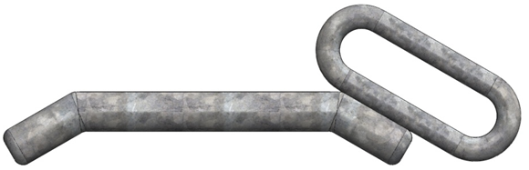
4.1.2 Service pin type 1 – 25mm for chain/round sling suspension
Service pin Type 1 should be used in the chain during normal operation.
For suspensions using only chain, Service pin Type 1 is also used during operations such as raising and lowering. Service Pin Type 1 can also be used with round sling suspensions.
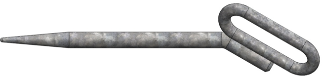
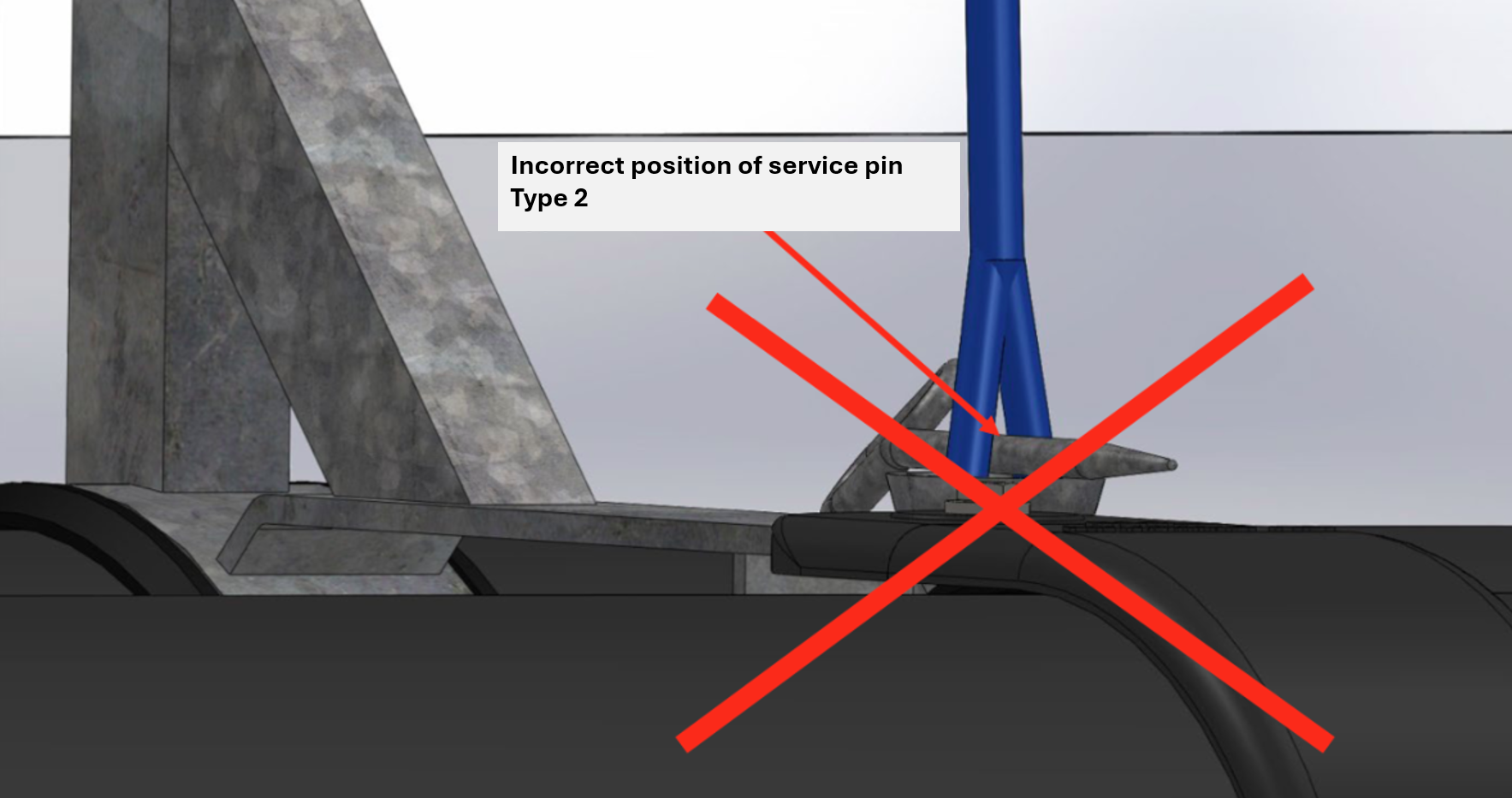
4.1.3 Service pin type 2 – 18mm for rope/round sling suspension

Service pin type 2 is only used during operations where the sinker tube suspension consists of fiber ropes or round sling.
4.1.4 Duplex pin for round sling suspension
Duplex pin can only be used for sinker tube suspension with round slings.
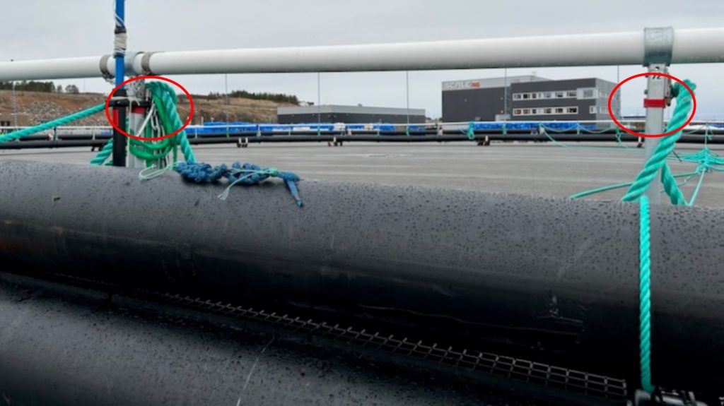
4.1.5 Position marking for the final butt fusion weld on the sinker tube
Red ribbons must be attached to the two brackets on the floating collar located on either side of the final butt fusion weld of the sinker tube. This is done to ensure that lifting the sinker tube is not started or ended at this point, as it may cause damage or bending of the sinker tube.
4.2 Installation when using Midgard system
When the floating collar is equipped with the Midgard system and during normal operation, it is only necessary to use a safety shackle at the end of the chain on the manual sinker tube suspensions. Manual suspensions should have approximately 70 cm of slack during daily operation when using the Midgard system. The slack can be adjusted using a pin or shackle.
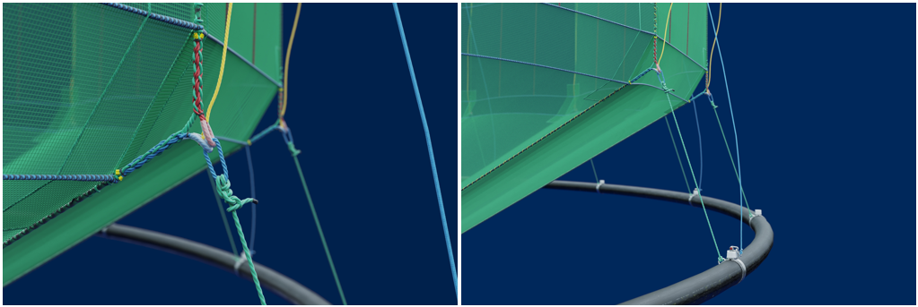
4.3 Attachment to the net
Attachment of the net to the suspension system should only be done by using the attachment loops on the bottom rope or the Hs3+ connection point that continues from the lifting rope (where the lifting rope continues as cross rope).
The sinker tube must be designed for use with the specific net.
The net certificate contains information about the approved suspension system from the design phase.
The suspension system must be installed in such a way that it does not cause chafing on the net.
4.3.1 Mounting and dimensions of sinker tube attachment rope
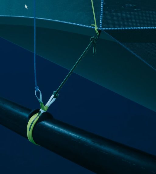
The sinker tube attachment rope is attached/choked between the net’s bottom rope or the Hs3+ connection point and sinker tube bracket with U-bolt, chain loop or Y-strap.
Dimensions of sinker tube attachment rope:
- Maximum distance from the net loop (Hs3+ connection point), rope ring or round sling to attachment of the sinker tube is 4,0 meters.
- Minimum distance from the net loop (Hs3+ connection point), rope ring or round sling to attachment of the sinker tube is 4,0 meters.
Ensure equal spacing and even load distribution on all attachment points between the net and sinker tube (suspension system).
NB! The dimension of the sinker tube attachment rope must be smaller than the dimension of the net loop/ear.
Example where ScaleAQ supplies sinker tube and net: Minimum 22 mm 3-strand rope with 7 tons MBL as sinker tube attachment rope must be used when the net loop/ear is 24 mm or more.
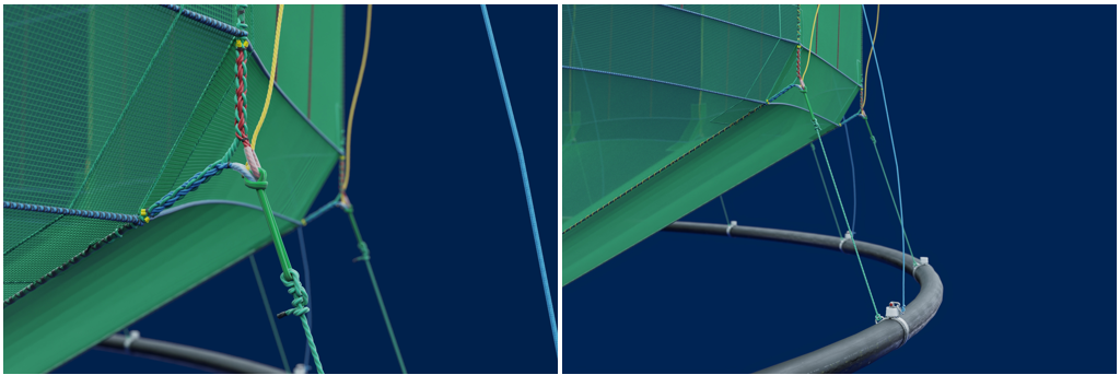
4.3.2 Attachment of net to sinker tube with Y-strap and stoppers
The net can also be attached to the sinker tube with Y-strap and stoppers as visualised in Figure 4.9.
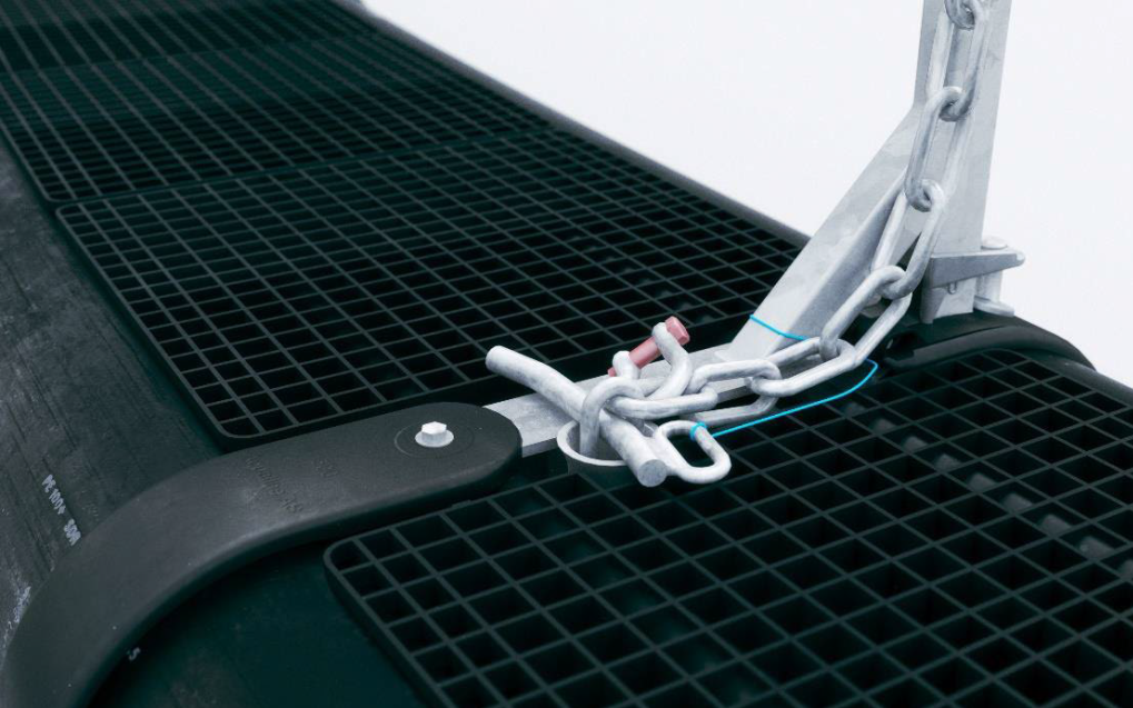
4.4 Securing sinker tube suspension when using standard net
When using a standard net, where the rope loops are not dimensioned to bear the load from the sinker tube, the load from the sinker tube is distributed to the sinker tube suspensions. When doing this, double securing of the suspension must be carried out by using either:
- Service pin type 1 (thick) + shackle or
- Shackle + shackle (both 4,75t trawl pin, 6,5t H-shackle and larger shackle are approved).
Double securing is achieved by placing a shackle (secondary securing) in the first available chain loop above the loop with the thick service pin or shackle (primary securing).
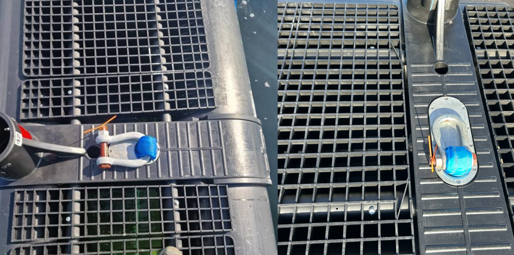
4.5 Securing sinker tube suspension in rope/round sling on plastic brackets
If the sinker tube suspension consists only of rope or round sling at the top on plastic brackets, securing with a single shackle is sufficient, as visualised in Figure 4.11.
It is important that the shackle is in contact with either the steel support plate or the bearing ring in the lower part of the plastic bracket.
A service pin alone is not approved as a securing method. In such cases, a shackle must also be used for double securing.
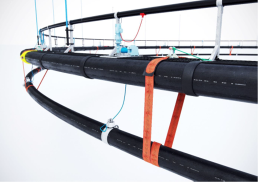
5 Installation at site
5.1 Preparation of sinker tube
The sinker tube is delivered laced and placed on top of the floating collar. Before the bridles are permanently attached to the floating collar, the sinker tube must be positioned underneath the floating collar.
- Sinker tube suspensions must only be attached to brackets designed for this purpose.
- Ensure that all sinker tube suspensions are secured to the floating collar using service pins or shackles to prevent uncontrolled lowering.
- Ensure that sinker tube ropes for net attachment are installed.
- Loosen the sinker tube suspensions that are temporarily hung on the posts of the floating collar; these should be coiled in such a way that the sinker tube can descend freely.
- Personnel must be positioned inside the sinker tube, near the handrail. Unnecessary personnel should not be present on the floating collar during this operation.
- Remove the lashings on the sinker tube so it can be lowered. Remove the loose lashings first.
- Push the bottom ring off the floating collar.
- Remove any transportation restraints on the sinker tube and dispose of them properly.
- The sinker tube should now hang just beneath the floating collar.
- The bridles can now be permanently attached.
- The net is then installed, as described in the net supplier’s user manual.
5.2 Installation of the net to the sinker tube
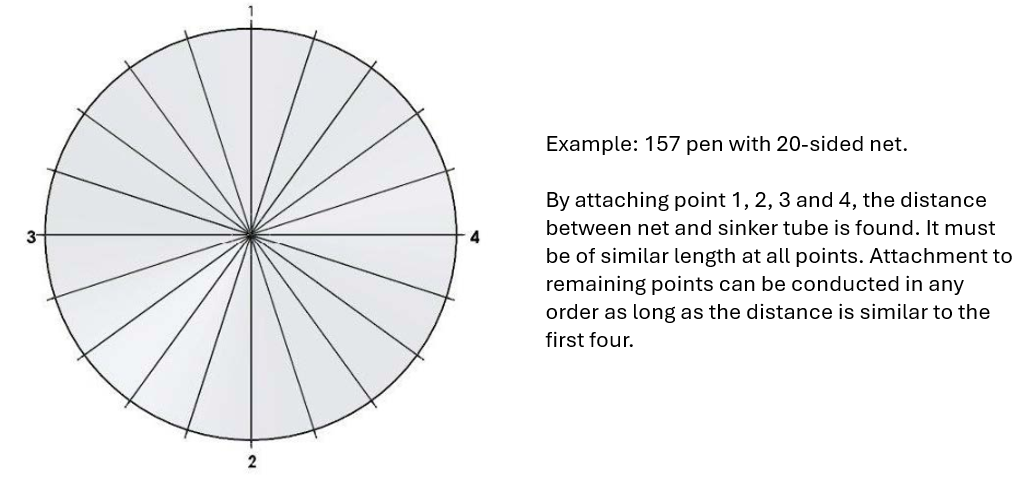
The net is attached to the sinker tube ropes at the designated net attachment points or any sliding blocks. The bottom of the net must be centered relative to the sinker tube (see example below), and no contact between the net and the sinker tube should be possible.
5.3 Inspection after installation

It is critical to perform a check after the sinker tube and net are installed and lowered to their operating position.
ScaleAQ recommends a general visual inspection of the outer net and sinker tube system after installation. This inspection should focus on the following:
- Interface with the floating collar
- Interface with the suspension system
- Connection points for rope terminations
- Wear, damage and holes in the net
6 Use
6.1 Use and securing of chain, rope and cables
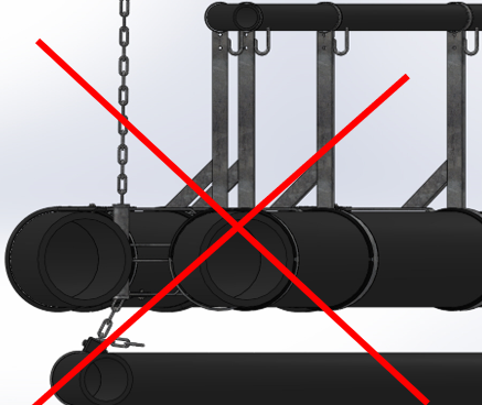
Chain, rope and cables must be used and stored responsibly to prevent damage to the floating collar, net, mooring, and extra equipment. It is especially important that chains, ropes, or cables do NOT hang between floating collar pipes where they may damage load-bearing steel rods, chains, or fiber ropes.
This is particularly critical on pens with fiber rope-based load-bearing systems.
6.2 Lifting of sinker tube
- Lifting of the sinker tube should be done gradually, with 5 meters (maximum 8 meters) lifted per sinker tube suspension per pass around the floating collar. Ensure that net lines do not catch on anything that might damage the net.
- The sinker tube can be raised to approximately 1 meter below the floating collar.
- The sinker tube suspensions are secured with service pins.
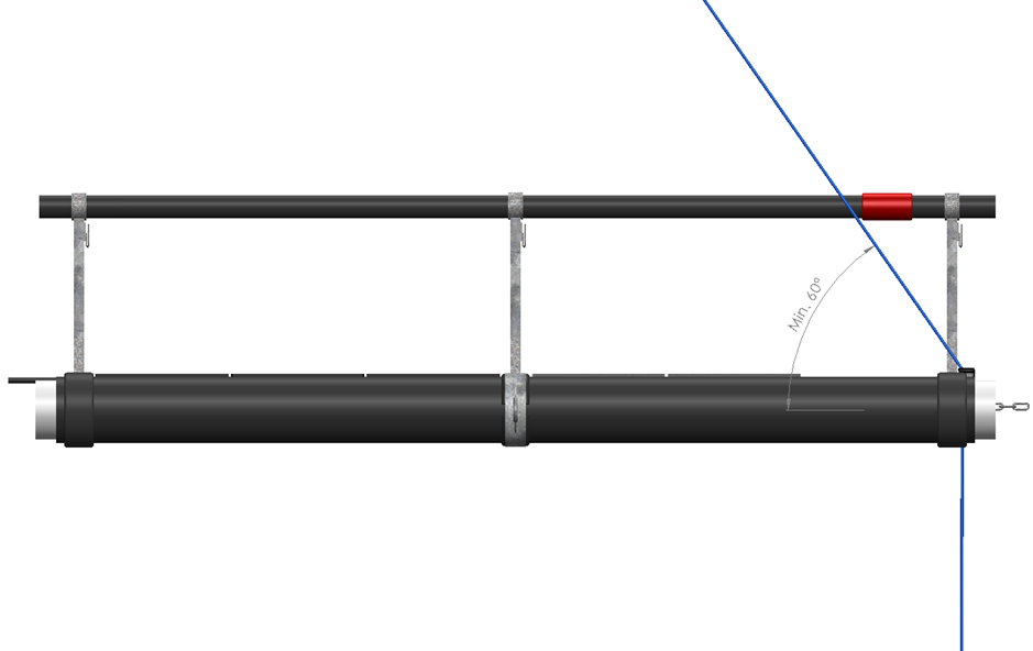
- The angle of fiber rope must not be less than 60° when lifting or lowering the sinker tube. The angle of chain should be approximately vertical.
- During installation/removal of the net, only one point may be lifted at a time under the floating collar. The sinker tube must not be lifted in a way that causes it or its components to become pinched, to avoid damage to sinker tube pipes, sinker tube suspension, winch rope and floating collar/load-bearing system.
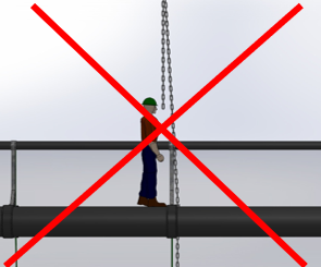
- The pen must never be lifted using the bottom ring suspensions under any circumstances.
6.3 Lowering of sinker tube
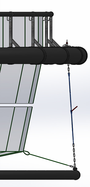
- Use a fiber sling in the bottom eye of interconnected loops in fiber rope, and hoist until the service pin can be released. For sinker tube suspension with permanently mounted round slings, Service Pin Type 1 must be used. See Figure 6.3. The sinker tube must NOT be lifted using these round slings.
- Lower the ring in a controlled manner until the rope can be locked with a service pin in the lowest eye at the most appropriate level. Lowering of the sinker tube should be done in steps of 5 meters (maximum 8 meters) per sinker tube suspension per round of the floating collar. Ensure that net lines do not catch anything that could damage the net.
- The angle of the chain/rope must not be lower than 60° during lifting and lowering operations.
- See chapter about operational positioning.
It is critical that an inspection is performed after the sinker tube and net are lowered to operating position.
ScaleAQ recommends a general visual inspection of the external net and sinker tube system after lowering. This inspection should focus on the following:
- Interface with the floating collar
- Interface with the suspension system
- Connection points for rope terminations
- Wear, damage and holes in the net
6.4 Distributing of sinker tube load
During operation, the sinker tube must at all times be attached to all sinker tube suspensions with evenly distributed load. The number of sinker tube suspensions depends on the type of floating collar and suspension system.
6.5 Cleaning
After each production cycle of fish, it is common to clean the pen and sinker tube. Specialized washing rigs are often used to remove biofouling and shell growth.
If a crane is used, ensure that the floating collar and sinker tube are securely fastened in the lifting slings, and do not stand under suspended loads.
When using disinfectants or chemicals, ensure that these do not damage the pen’s components.
6.6 Precautions for launching and uptake

During uptake or launching, the sinker tube must be laced on top of the floating collar.
Space requirements: The area must accommodate the floating collar with sinker tube and provide at least 10 meters of free space around it.
For uptake (to land), cranes or other appropriate lifting equipment may be used (see Chapter 7.3). Lifting the entire floating collar requires large cranes and is generally not practical for collars of 90 meters in circumference or larger.
The most common method involves a combination of lifting and pulling force.
The floating collar may be ovalized by tensioning ropes across it to make it easier to bring ashore.
Be careful to avoid creating sharp bending radii in the pipes that could cause them to break.
Maximum allowed increase in diameter during handling: 15%.
7 Inspection and maintenance
7.1 Precautions

If the customer wants to make changes to or service the sinker tube system using third parties instead of ScaleAQ, the following requirements apply:
- Training in inspection and maintenance of the sinker tube system.
- Training will be provided by ScaleAQ and leads to qualification of personnel for sinker tube service and inspection.
- Only ScaleAQ-approved parts must be used when replacing any part or the entire sinker tube system.
ScaleAQ assumes responsibility only when the sinker tube system, spare parts, and service personnel are approved by ScaleAQ.
Operators responsible for the floating collar and sinker tube system must only use ScaleAQ-approved personnel for inspection and service.
7.2 Methods for inspection
- GVI = General visual inspection:
Visual inspection in which the inspector looks for obvious damages at a distance from the object. This can be performed with ROV or diver with a normal camera. - NVI = Near visual inspection:
Use of near vision camera or detection tool (e.g. ultrasound) to identify damage near the surface to the object. - DC = Dimension control:
Use of measuring tools to control dimensions. - MR = Modification / Replacement
7.3 Acceptance criteria for sinker tube quality standards
7.3.1 Tolerances for chain replacement
Mechanical wear tolerances for chain in sinker tube suspension:
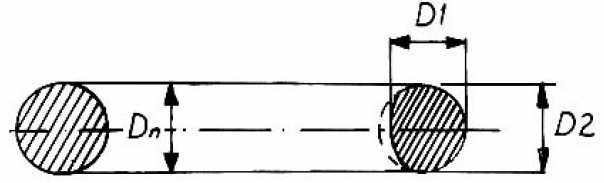
≤ 10% reduction of original material diameter, measured across two diameters (D1 and D2) at 90° offset.
This means the remaining diameter must be at least 90% of the nominal diameter (Dn).
| Chain dimension [mm] | Requirement to average diameter of used chain [mm] |
| 16 | 15.2 |
| 19 | 18.0 |
| 22 | 20.9 |
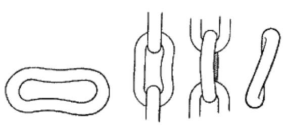
Chains must also be replaced if exposed to severe corrosion or show visible damage such as wounds, cracks or wear.
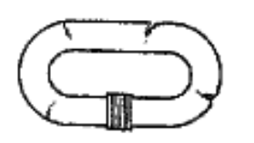
Chains must be replaced if they show visible deformations such as elongation, bending, or twisting.
7.3.2 Wear tolerances for bolts and shackles
Maximum wear tolerance for bolts and shackles: ≤ 20 % of original material diameter, measured over two diameters (D1 and D2), offset by 90°. This means the remaining diameter must be at least 80% of the nominal diameter Dn.
Spot-check 4 bolts in a cross-pattern on the floating collar. These should be disassembled and checked for corrosion and abrasion. Log in service report which bolts were inspected to avoid repetition in the next inspection. Results from rod bolt measurements must be recorded in the inspection report. Also inspect for ovalization of bolt holes in the brackets.
7.3.3 Tolerances for fiber ropes
Wear tolerance for fiber ropes: ≤ 1 strand/part.
7.3.4 Tolerances for plastic pipes
If a plastic pipe shows damage to more than 20% of its wall thickness, ScaleAQ must be contacted to determine whether repair or replacement is necessary.
| TYPE | SDR | Wall thickness [mm] | Max. damage depth [mm] |
| 315 | 11 | 28.6 | 5.7 |
| 400 | 11 | 36.4 | 7.3 |
| 450 | 11 | 40.9 | 8.2 |
| 500 | 11 | 45.5 | 9.1 |
7.3.5 Tolerances for sinker tube clamps
| Type | Dim. clamp | Dim. ear | Dia. bolt hole | Max. dia. bolt hole | Min. thickness ear |
| 315 mm | 150×15 mm | 90×20 mm | 28 mm | 33.6 mm | 16 mm |
| 400 mm | 200×15 mm | 120×25 mm | 34 mm | 40.8 mm | 20 mm |
| 450 mm | 200×15 mm | 120×25 | 34 mm | 40.8 mm | 20 mm |
7.3.6 Tolerances for sinker tube adapter
Wear tolerance for bolts: ≤ 20% of original material diameter, measured over two diameters (D1 and D2), offset by 90°. The remaining diameter must be at least 80% of the nominal diameter Dn.
7.3.7 Tolerances for Y-straps
If there are signs of extensive wear or damage, the Y-strap must be replaced immediately. Examples of such damage: tears, cuts or stitching failure on the strap solution.
7.4 Inspection and maintenance
| MAINTENANCE MUST FOLLOW THE GIVEN INTERVALS | MTHLY. | EVERY 3. MTH. | GENERATION CONTROL | ||
| Checkpoint | What | How | |||
| 1 | Sinker tube pipe | Check sinker tube pipe for bends, cuts and fractures. | X | ||
| 2 | Sinker tube suspension | Ensure that the sinker tube suspension is in its operational position: the net should be unloaded and the sinker tube should be hanging from the suspension points. Also check if the surface is excessively rough compared to new chain, due to corrosion or damage. | X | ||
| 3 | Sinker tube suspension and net | Look for signs of abrasion between the sinker tube suspension and the net. | X | ||
| 4 | Sinker tube suspension | Use a camera or diver to inspect the attachment between the net and the sinker tube. Check the sinker tube suspension for any damage. | X | ||
| 5 | Sinker tube chain | Inspect the sinker tube chain for corrosion, cracks and damage as described in section 7.3.1. A rough surface may also damage the net if contact occurs between the chain and the net. | X | ||
| 6 | Sinker tube clamp | Check the connection between the sinker tubeg suspension and the sinker tube: clamps, bolts, chains, and plastic protection. Refer to tolerances. | X | ||
| 7 | Y-strap solution | Inspect the Y-strap for wear, cuts, and ensure that both plastic stops are present and intact. | X | ||
| 8 | Fiber rope | Check ropes for chafing. Damaged ropes must be replaced. Refer to tolerances. | X | ||
The person performing inspection and maintenance must be qualified for the task and must be familiar with and have understood the product’s user manual.
After weather events, currents, or incidents that may have subjected the equipment to forces beyond normal levels, check point 3 and 4 must be reviewed.
8 Transport and storage
8.1 Transport/towing
For transport/towing of pen with sinker tube lying on top of the walkway, guidelines in Figure 8.1 for securing the sinker tube must be followed.
8.2 Storage for short periods
When storing the pen and sinker tube without the net installed, the sinker tube must be stored at a minimum depth of 2.5 meters below the pen.
Storage at this minimum depth is only recommended for short periods, maximum 3 days, and only under calm sea/weather conditions during temporary storage. Temporary storage of the sinker tube at depths less than the minimum depth of 2.5 meters can cause damage to the pen, chain/rope, sinker tube, and sinker tube clamps.
8.3 Storage over longer periods
For storage over longer periods, 4 alternatives can be used.
8.3.1 Alternative 1 – Temporary storage by lowering the sinker tube (for pens without winch)
The sinker tube is lowered as far as the sinker tube suspension allows to reduce jerk and wear damage on the sinker tube and its suspension due to rough seas/bad weather.
During temporary storage, the sinker tube must be suspended from all sinker tube suspension points with evenly distributed load to avoid abnormal point loads on the sinker tube and its attachments.
This applies only to pens without mounted winches.
If the pen has winches mounted, it is critical to ensure that the winches are not bearing any load during the temporary storage of the sinker tube. This is achieved by either following alternative 2: Temporary Storage Using Winch Rope, or by installing manual sinker tube suspensions at the same location as the winch ropes. In this case, the manual suspensions shall carry the load during storage.
8.3.2 Alternative 2 – Temporary storage using winch ropes (for pens with winch)
For pens equipped with winches, it is recommended to store the lowered sinker tube using winch ropes, as illustrated in Figure 8.3 and 8.4.
For temporary storage of winch ropes, a Dyneema loop must be spliced into the winch rope 6 meters from the top. If retrofitting a loop into an existing winch rope, this can be performed by ScaleAQ, or by following the mounting manual “Mounting of Dyneema loop in winch rope” attached to this user manual.
See the appendix “Temporary storage of lowered sinker tube” for guidance on using winch rope for temporary sinker tube storage.
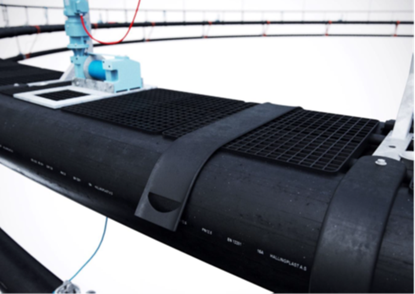
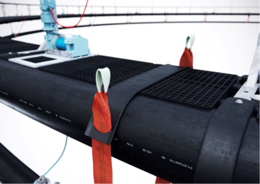
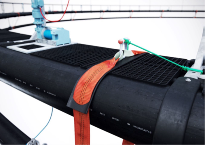
8.3.3 Alternative 3 – Temporary storage straps
A complete set of temporary storage straps for storing the sinker tube can be ordered from ScaleAQ. The set includes a 9-meter 5-ton webbing strap, a 28-ton mooring shackle, and a fender for the flat strap. The number of storage straps per pen depends on the floating collar’s circumference, as outlined below:
- 120 m – 16 pcs.
- 135 m – 16 pcs.
- 157/160 m – 20 pcs.
- 200 m – 24 pcs.
Attachment of the straps can be done, for example, during cleaning of the floating collar in the cleaning rig or using appropriate tools such as a boat hook.
After use, the temporary storage straps must be stored in a dry place and out of direct sunlight.
The figures below illustrate the correct installation of the storage straps. Figure 8.5 shows a fully installed strap. Figures 8.5–8.8 describe the correct connection of the straps and how to secure them to the floating collar’s brackets. If there are any questions related to the description of the installation, please contact ScaleAQ AS.
8.3.4 Alternative 4 – Storage of sinker tube on top of the pen
The sinker tube can be stored on top of the floating collar. For such storage, spacers must be used between the sinker tube and the floating collar to prevent chafing between components. The sinker tube must be secured with appropriate equipment. If the floating collar has winches, the sinker tube must be secured to make sure there is no contact between the sinker tube and the winches. During temporary storage, the floating collar with the associated sinker tube suspensions must be inspected weekly and after rough weather to detect any wear damage or faults related to the storage.
9 Producer and product identification
| HEAD QUARTERS | |
| Scale Aquaculture AS | Telephone: +47 73 80 99 30 |
| Beddingen 16 | E-mail: post@scaleaq.com |
| 7042 Trondheim | www.scaleaq.com |
| CONTACT INFORMATION | |
| Anders Sletten, Product Manager Cages | anders.sletten@scaleaq.com |
| Lars Andreas Larsen, Head of Pens & Nets | lars.andreas.larsen@scaleaq.com |
9.1 Documentation
Information about the sinker tube is found in the product certificate for the pen from ScaleAQ. The product certificate contains information about the dimension class, validity period, and details about the pen and the materials it is made from. This product certificate must be available to the holder of the aquaculture permit. See example in Appendix 1.
10 Revision history
| Rev. | Changes | Date |
| 1 | The user manual is revised to meet new requirements in NS 9415: 2021. | 01.09.2025 |
| 2 | Chapter 4.3 Attachment to the net updated with max/min length of the sinker tube attachment rope and other details. | 12.09.2025 |
11 References
| /1/ | NYTEK23 |
| /2/ | NS 9415:2021 |