Midgard Winch system
Manuals
Midgard Winch system
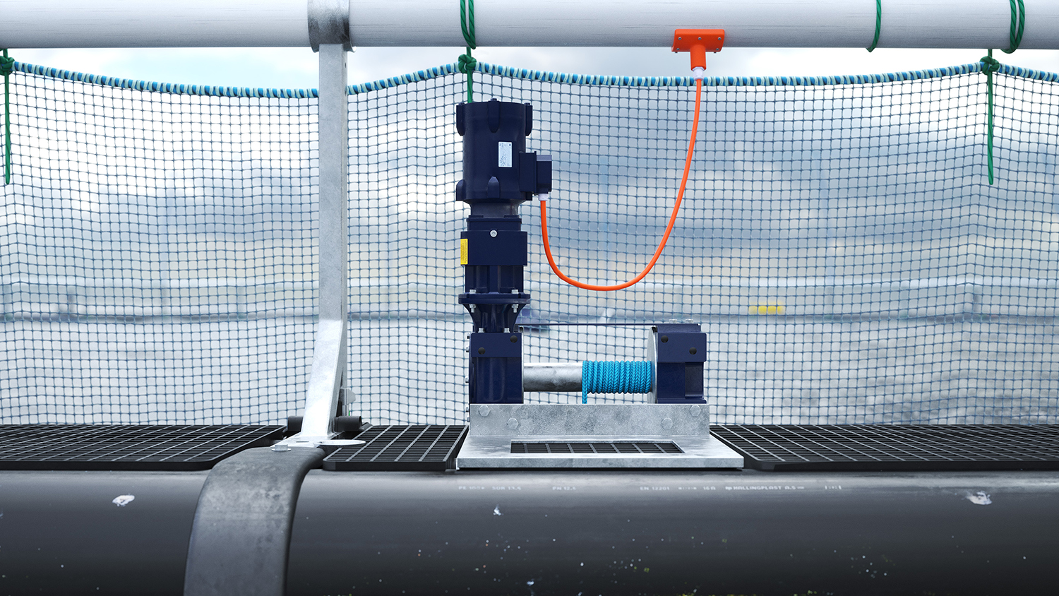
Table of Contents
1 Summary with an overview of the component and key points related to escape prevention
1.1 General definitions
| Aquaculture farm | Installation for the farming of fish. |
| Design working life | Assumed period for which a structure or part of it is to be used for its intended purpose with anticipated maintenance but without major repair being necessary. |
| Operation | Fish farming at site, including all installation and operation activities performed at the site while fish farming is in progress, and that are of relevance to the escape prevention of fish. |
| Extra equipment | Equipment that is not a main component. |
| Inspection | Systematic inspection/examination, usually visual, to ensure that the equipment satisfies the requirements. |
| Floater | Construction with the main function of providing Structure whose main function is to provide an enclosure with buoyancy and/or stiffness. |
| Anchoring system | System of lines and bottom attachments with the main function of keeping the aquaculture farm or raft in position. |
| Bridles | Anchoring line between the floater and the anchoring system. |
| Main component | Part of an aquaculture farm that holds one or more of the installation’s load bearing main functions. Example: Floater, anchoring system, raft and enclosure. |
| Enclosure | Net or other system of load bearing parts that form a barrier between the farming volume in a production unit and the surrounding water volume. |
| Bracket | Component on floats that holds PE pipes Component keeping the inner and outer floating collar pipes together. |
| Capelin | Weight or other device attached to the net to achieve the intended shape. Centre weight is attached beneath the bottom centre of the net-cone. |
| Cage | Floater with enclosure. |
| NS9415:2021 | Standard which sets out functional requirements for floating aquaculture farms and will be fundamental for stakeholders in the aquaculture industry, such as authorities, supervisory bodies, designers, suppliers, actors within R&D and manufacturers, as well as aquaculture farm owners. |
| NYTEK23 regulation | Governing Regulation for Fish Farming in Norway. |
| Product certificate | Document confirming that the net is produced in accordance with requirements in NYTEK23 and NS9415:2021. |
| Suspension system | Weight, sinker tube or similar used to keep the three-dimensional shape of the net. |
1.2 Introduction
This user manual provides a description of the Midgard Winch System supplied by ScaleAQ and guidance for safe use to prevent the escape of fish.
The Midgard Winch System has been developed for efficient raising and lowering of sinker tube and net systems. The winch system must not be used for purposes other than those described in this user manual.
The user manual has been prepared in accordance with NYTEK23 and applies to all versions of the ScaleAQ Midgard Winch System.
ScaleAQ accepts no responsibility for any claims arising from use beyond that described in this user manual.
2 Description of Midgard Winch System and its components
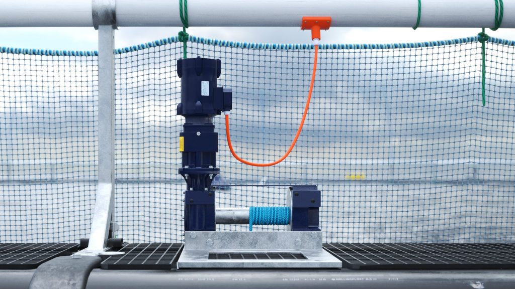
The Midgard Winch System is a system of electrically driven winches mounted on the pen for the purpose of raising and lowering the sinker tube/net system in the cage. The winch system can consist of up to 12 winches in the same system that can be operated simultaneously and ensure even lifting around the entire floating collar.
The purpose of the Midgard winch system is to ensure fast and efficient sinker tube operations with reduced risk for the operators. The winch system eliminates the need for vessels with powerful cranes, and only requires a power supply to operate,
The Midgard winch system supplied by ScaleAQ mainly consists of:
- Up to 12 (usually 10) Midgard winches with motor and winch rope distributed around the pen (Figure 1.1)
- Winch rope in HMPE (8-15mm) that runs from the winch drum to either the sinker tube or the net
- Junction cabinet mounted on the pen that serves as the central connection point for all winch cables
- Control cabinet with frequency converters and remote control for winch operation
2.1 Midgard Winch
The Midgard winch is a powerful and waterproof winch designed and developed specifically for long lifetime in aquaculture and efficient cage operations.
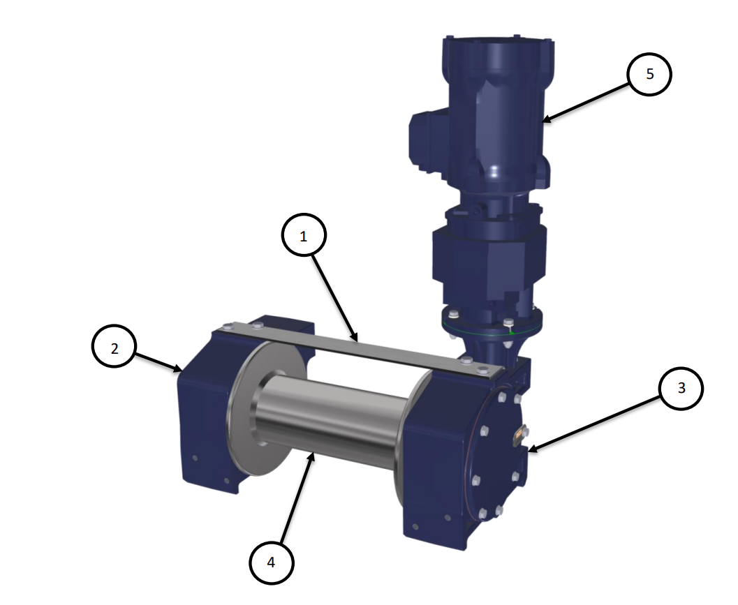
The components of the Midgard Winch are shown in Figure 2.1. The winch is equipped with a heavy duty worm gearbox [3] and drum [4] in duplex/stainless steel. The worm wheel and drum are driven by an electric motor [5] through a reduction gearbox. The drum is supported by a plain bearing [2] at one end, while the other end is connected to the worm gearbox [3]. A transport brace [1] holds the gear housing/plain bearing [2] and worm gearbox [3] together.
- Transport brace
- Gear housing and plain bearing
- Worm gearbox
- Drum
- Electric motor with gearbox
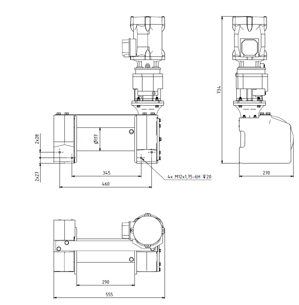
Dimensions for Midgard Winch are shown in Figure 2.2.
Mounting hole dimension: M12x1.75
Dimension hole for winch rope: 314x50mm
Midgard Winch is available in two different versions, version 1.0 and version 1.1. The difference between the versions is that version 1.1 is equipped with a different material quality on the drum that gives a higher permitted load and amount of rope on the drum than version 1.0. This is described in specification chapters 2.1.1 and 2.1.2.
Serial number version 1.0: up to and including 18041 + 18192 to 18626
Serial number version 1.1: 18042-18191 + 18627 onwards
2.1.1 Specification Midgard Winch 1.0
Reduction gearbox: Heavy duty axle and worm gearbox for long and trouble-free service life.
Drum: Drum in marine grade 316 stainless steel (1.4404).
Brake: The irreversible action of the worm and worm wheel ensures significant braking effect.
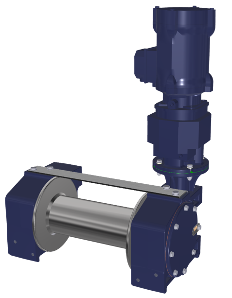
| MIDGARD WINCH 1.0 | |
|---|---|
| Pulling force | 1,200kg |
| First layer speed (no load) | 0.9 m/min |
| Rope diameter | 8mm to 15mm |
| Rope length, maximum allowed | See chapter 2.1.3 |
| Max running time | 30 minutes |
| Dimension, drum | Ø117mm, length 290mm |
| Weight, winch only | 52.5 kg |
| Weight, complete | 85kg |
| Amps, maximum | 4.5 Amp |
| Amper normal operation | 3.8 Amp |
| ELECTRIC MOTOR AND REDUCTION GEARBOX WINCH 1.0 | |
| Electric motor | 230 Volt, 50Hz, 3-phase |
| Engine type | Flange mounted, 160mm dia. flange |
| Motor speed | 1430 rpm |
| Engine power | 1.5 kW |
| Reduction | 12.96:1 (2-step) |
| Output torque | 131 Nm |
| Output speed | 109 rpm |
| Recommended generator size | 15 kW |
| Power supply fuses | 32 Amp |
| Contact type | 3-phase |
| Volt options power supply | 230V / 400V |
| Gear oil | ALPHASYN EP 220 |
| WORM GEARBOX WINCH 1.0 | |
| Reduction | 48:1 |
| Gear oil | Shell Spirax S3 AS 80W-140 |
2.1.2 Specification Midgard Winch 1.1
Reduction gearbox: Heavy duty axle and worm gearbox for long and trouble-free service life.
Drum: Drum in duplex steel (1.4462).
Brake: The irreversible action of the worm and worm wheel ensures significant braking effect.
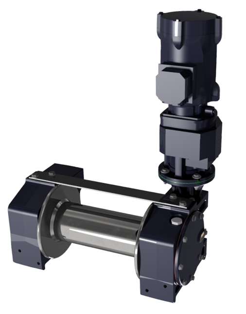
| MIDGARD WINCH 1.1 | |
|---|---|
| Pulling force | 1,700 kg |
| First layer speed (no load) | 0.9 m/min |
| Rope diameter | 8mm to 15mm |
| Rope length, maximum allowed | See chapter 2.1.3 |
| Max running time | 60 minutes |
| Dimension, drum | Ø117mm, length 290mm |
| Weight, winch only | 52.5 kg |
| Weight, complete | 85 kg |
| Amps, maximum | 4.5 Amp |
| Amper normal operation | 3.8 Amp |
| ELECTRIC MOTOR AND REDUCTION GEARBOX WINCH 1.1 | |
| Electric motor | 230 Volt, 50Hz, 3-phase |
| Engine type | Flange mounted, 160mm dia. flange |
| Motor speed | 1415 rpm |
| Engine power | 1.5 kW |
| Reduction | 12.96:1 (2-step) |
| Output torque | 131 Nm |
| Output speed | 109 rpm |
| Recommended generator size | 15 kW |
| Power supply fuses | 32 Amp |
| Contact type | 3-phase |
| Volt options power supply | 230V / 400V |
| Gear oil | ALPHASYN EP 220 |
| WORM GEARBOX WINCH 1.1 | |
| Reduction | 48:1 |
| Gear oil | Klübersynth MEG 4-460 |
2.1.3 Permitted amount of rope for Midgard system
Table 4 shows the amount of Dyneema/HMPE rope permitted on Midgard Winch.
The given amount is based on optimal spooling and that the number of layers of rope on the drum is no more than a maximum of 3 layers for winch 1.0, and a maximum of 4 layers for winch 1.1.
Max load for Midgard winch 1.0 is 1200kg, except when using 8 or 10mm rope.
Max load for Midgard winch 1.1 is 1700kg.
| Rope diameter [mm] | Amount of rope on drum [m] Midgard Winch 1.0 | Amount of rope on drum [m] Midgard Winch 1.1 |
|---|---|---|
| 8 | 42, max load 800kg | 60 |
| 10 | 35, max load 1000kg | 50 |
| 11 | 32 | 46 |
| 12 | 30 | 43 |
| 15 | 25 | 36 |
2.1.4 Permitted amount of rope for Subsea system
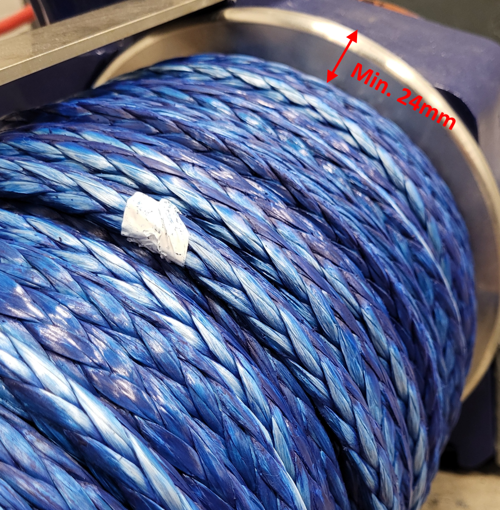
For the ScaleAQ Subsea system, the permitted amount of rope on the drum is 50m.
This applies under the following conditions:
- The winch is of type Midgard Winch 1.1
- Winch rope 12mm Dyneema/HMPE
- Max 6 layers of rope
- Minimum 2x rope diameter (24mm) clearance between top of the flange and rope
2.1.5 Winch bracket
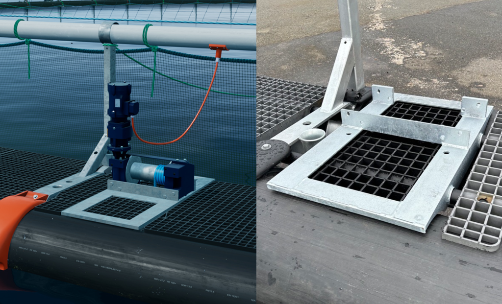
The Midgard winches are attached to the winch bracket using 8 pcs. M12x30 bolts as shown in Figure 2.6. The winch bracket is a robust steel frame with a fairlead for the winch rope, which is mounted to the floating collar by threading walkway pipes through holes in the winch bracket.
2.1.6 Rope guides
ScaleAQ recommends rope guides as shown in Figure 2.7. This rope guide has item number 506666.
The rope guide can be retrofitted to the ScaleAQ winch bracket, and will replace previous variants “fairleads”.
Contact ScaleAQ for ordering and manual for retrofitting rope guides.
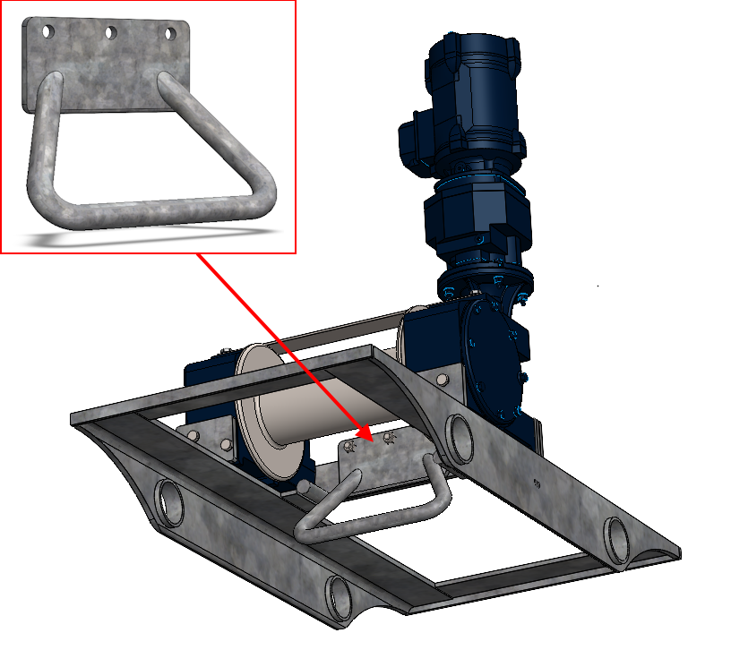
2.1.7 U-bolt for winch bracket
For more exposed locations, a U-bolt for the winch bracket can be retrofitted. This is designed and developed for harsh and exposed locations.
The winch bracket U-bolt should only be installed by ScaleAQ personnel. See the installation manual in the appendix.
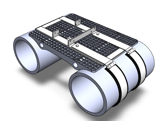
2.1.8 Handrail lock
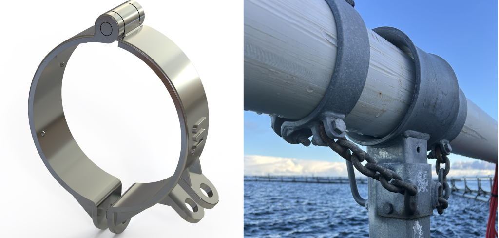
To prevent handrail pipes containing winch cables from rotating, a handrail lock must be installed. The latest version of the handrail lock is shown in Figure 2.9.
2.2 Connection cabinet
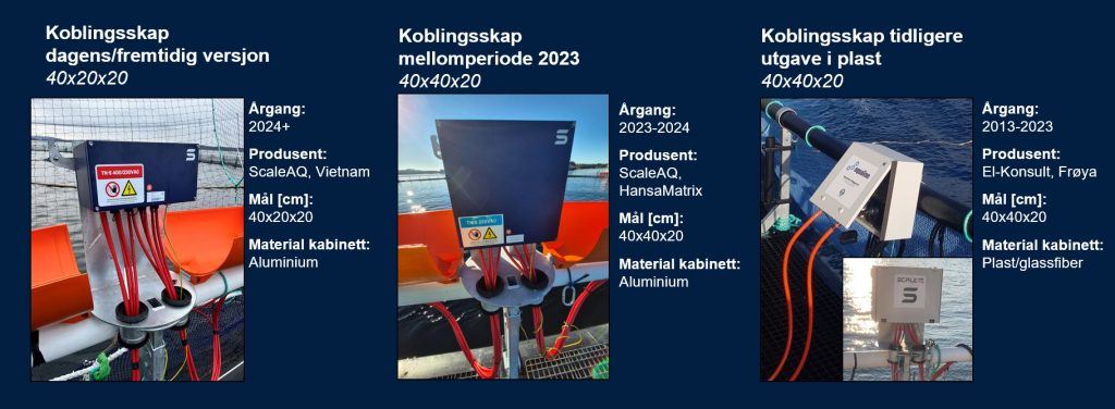
All winches on the pen are connected by electrical cables that are routed through the handrail pipe on the pen, which are ultimately connected in a connection cabinet as shown in Figure 2.10.
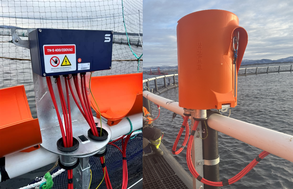
The connection cabinet is attached to the pen’s handrail post using ScaleAQ’s power cabinet module and universal holder for extra equipment. The power cabinet module contains a plastic cover for protection against water as shown in Figure 2.11.

The latest version of the ScaleAQ connection cabinet comes in powder-coated aluminium and has connectors adapted to cables and connectors for the latest version of the control cabinet. Earlier versions of the connection cabinet in plastic/glass fibre have cables and connectors adapted to control cabinets in the same design and version. See Figure 2.12 for an overview of connection cabinet versions, sizes and connectors.
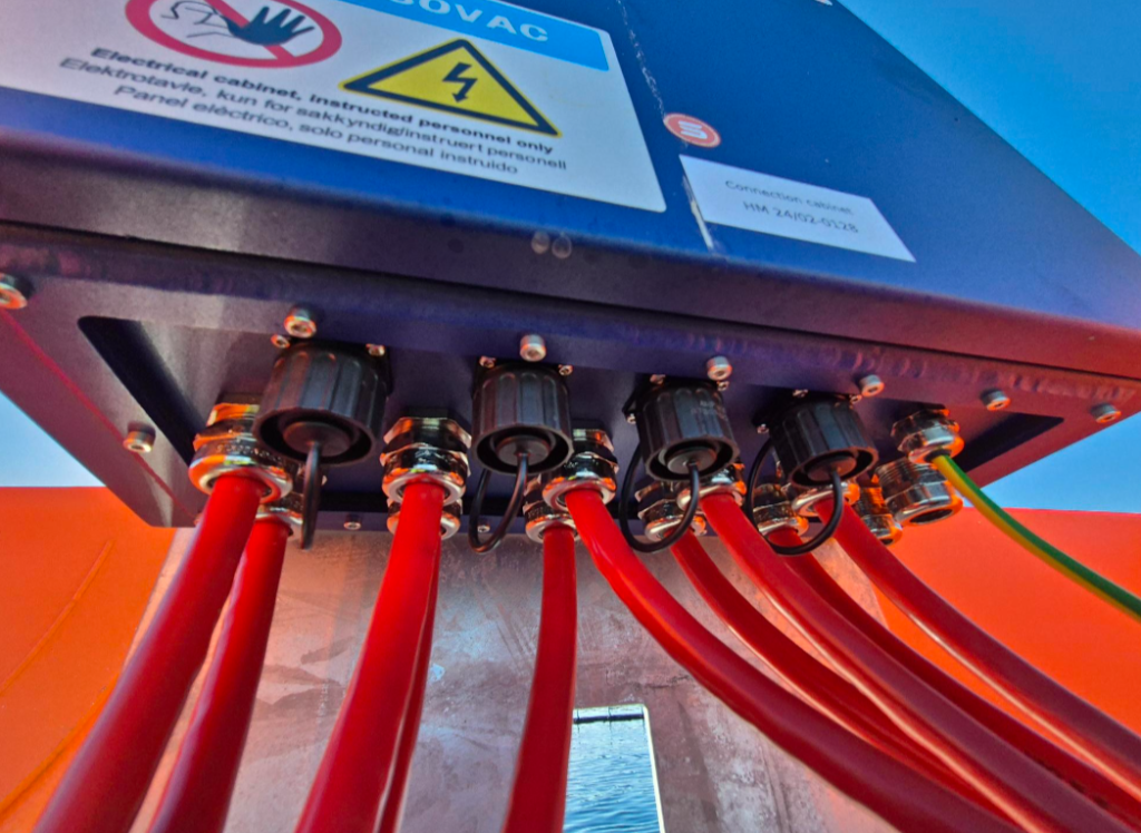
⚠️ NOTE! Plastic connectors as shown in Figure 2.13 require careful handling. This applies in particular to 40x40x20mm connection cabinets that start with the serial number “HM”. These connection cabinets have little space for connection and little visibility, in addition to connectors being orientated randomly. This can lead to plastic breakage if handled roughly.
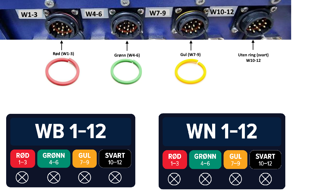
To operate the Midgard winches, connect to the ScaleAQ connection cabinet by using ScaleAQ control cabinet in the connectors as shown in Figure 2.14.
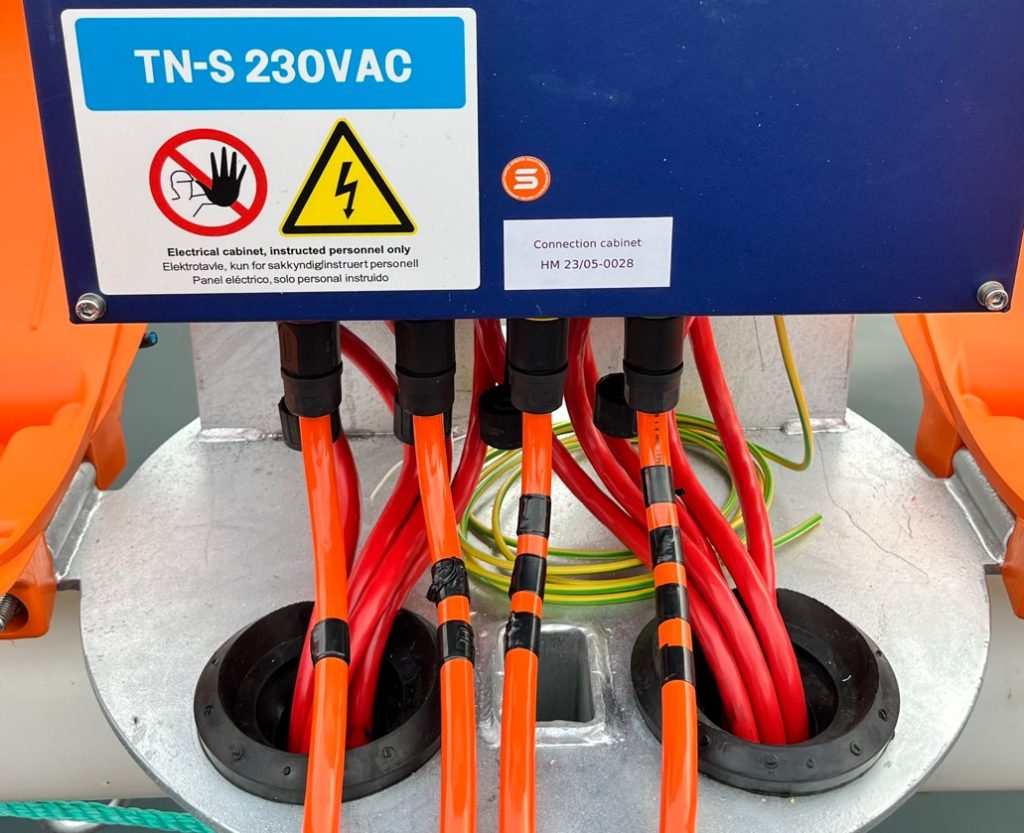
When connecting cables in the Midgard connection cabinet on the pen, follow the labelling instructions shown in Figure 2.15.
2.3 Control cabinet
ScaleAQ control cabinets are used to operate Midgard Winches.
Control cabinets are available in both 230V and 400V.
There are mainly two different versions of the Midgard control cabinet, as shown in Figure 2.16:
- New aluminium version from 2024 (remote control RemDevice)
- Older version in grey/white plastic (remote control Tele Radio)
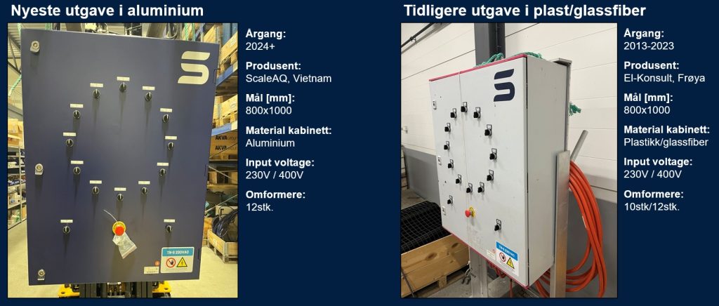
2.3.1 Control cabinet and remote control – Latest version
The new control cabinet has been upgraded with an aluminium cabinet that is powder-coated and waterproof.
The control cabinet can run locally on the cabinet and be controlled remotely using the supplied remote control.
Latest version of remote controls has magnetic charging and easy operation to run desired winches, see Figure 2.17.
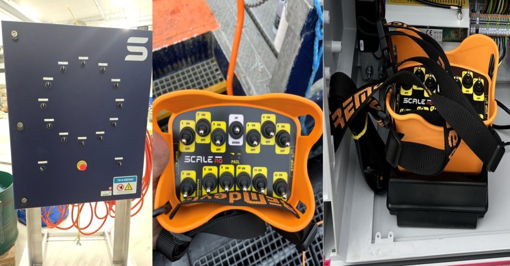
Remote control REMdevice with start-up guide is included with the latest version of the control cabinet. Please contact ScaleAQ if digital user guidance is required.
2.3.2 Control cabinet and remote control – Older version
Older Version Tele Radio remote control is an outgoing model, which is delivered on some older cabinets that are made of fibreglass.

2.4 Adapter type 2
Adapter Type 2 is used to connect the old version control cabinet (plastic/glass fibre) to the new version connection cabinet (aluminium blue).
The adapter box and cables are labelled red (1-3), green (4-6), yellow (7-9) and black (10-12) according to the standard for labelling connection cabinets.
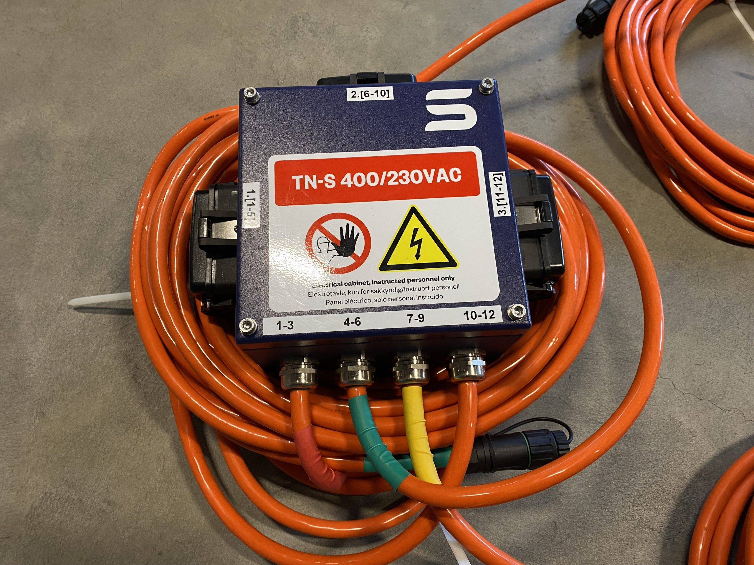

2.5 Adapter type 1
For cases where the old version connection cabinet on the pen is to be connected to the latest version control cabinet, ScaleAQ has available Adapter Type 1, see Figure 2.21.

3 Interaction with other components
The Midgard Winch System is designed and developed for use and interaction with ScaleAQ pens, nets and sinker tube systems.
For the use of other adjacent main components or extra equipment that may affect the Midgard Winch System and which are not covered by this user manual, ScaleAQ should be contacted.
3.1 Interaction pen and suspension system
Midgard Winch System is approved for ScaleAQ pens and pen dimensions 450, 500, 560 and 630 with associated sinker tube system.
Midgard Winch System is approved for environmental loads corresponding to the environmental load stated in the product certificate for the aforementioned ScaleAQ pens.
The Midgard winch system must at all times be mounted to the pen and sinker tube system as stated in this user manual.
During raising and lowering operations, the sinker tube must not be raised to a level where the sinker tube collides with the floating collar pipes.
During raising and lowering operations, the sinker tube must not be raised to a level where the winch rope comes into contact with the load bearing system of steel rods on the pen under high load. This can damage both the rod system and the winch rope. The guideline height for raising the sinker tube is a maximum of 1m below the floating collar pipes, but this will vary depending on the circumference of the sinker tube and weather conditions during the raising operation. Operators must monitor contact between the winch rope and rod system when raising the sinker tube.
3.2 Interaction with nets
The Midgard Winch System is designed and developed for use and interaction with ScaleAQ nets.
The Midgard Winch System is approved for use with certified nets from other suppliers, provided that this user manual is followed.
For interaction with Subsea nets, see separate user manual for ScaleAQ Subsea.
3.3 Interaction with permanent extra equipment
ScaleAQ must be contacted when using permanent extra equipment that may affect the integrity and capacity of the Midgard Winch System.
3.4 Interaction with temporary extra equipment
When using temporary extra equipment that may affect the integrity and capacity of the Midgard Winch System, ScaleAQ must be contacted.
4 Assembly and installation
4.1 Mounting the winch
Midgard winches must at all times be mounted in the ScaleAQ winch bracket, see section 2.1.5. Winches must be installed by ScaleAQ or personnel with expertise and training in Midgard winch systems.
4.2 Mounting the winch rope on the drum
- Pass the end of the rope through the hole in the drum until an end of approx. 30cm is sticking out on the other side of the hole. Wrap the rope around the drum and splice the free end of the rope together with the same rope as shown in Figure 4.1.
- The rope is then spliced with a minimum of 3 inserts.
- Pull the rope until the splice is even and smooth.
- Pull the rope around until the splice is inside the hole in the drum, see pictures in Figure 4.1.
- Rotate the drum and feed the rope evenly onto the drum.
- Tighten the rope moderately as the rest of the rope is spooled onto the drum. Make sure the layers are spooled evenly on the drum, as this will reduce the damage to the lower layers of rope when there is load on the rope.
- Avoid spooling the rope onto the drum at an angle larger than 15° relative to the winch. This reduces wear and tear on the rope.

4.3 Installation of winch rope to the sinker tube
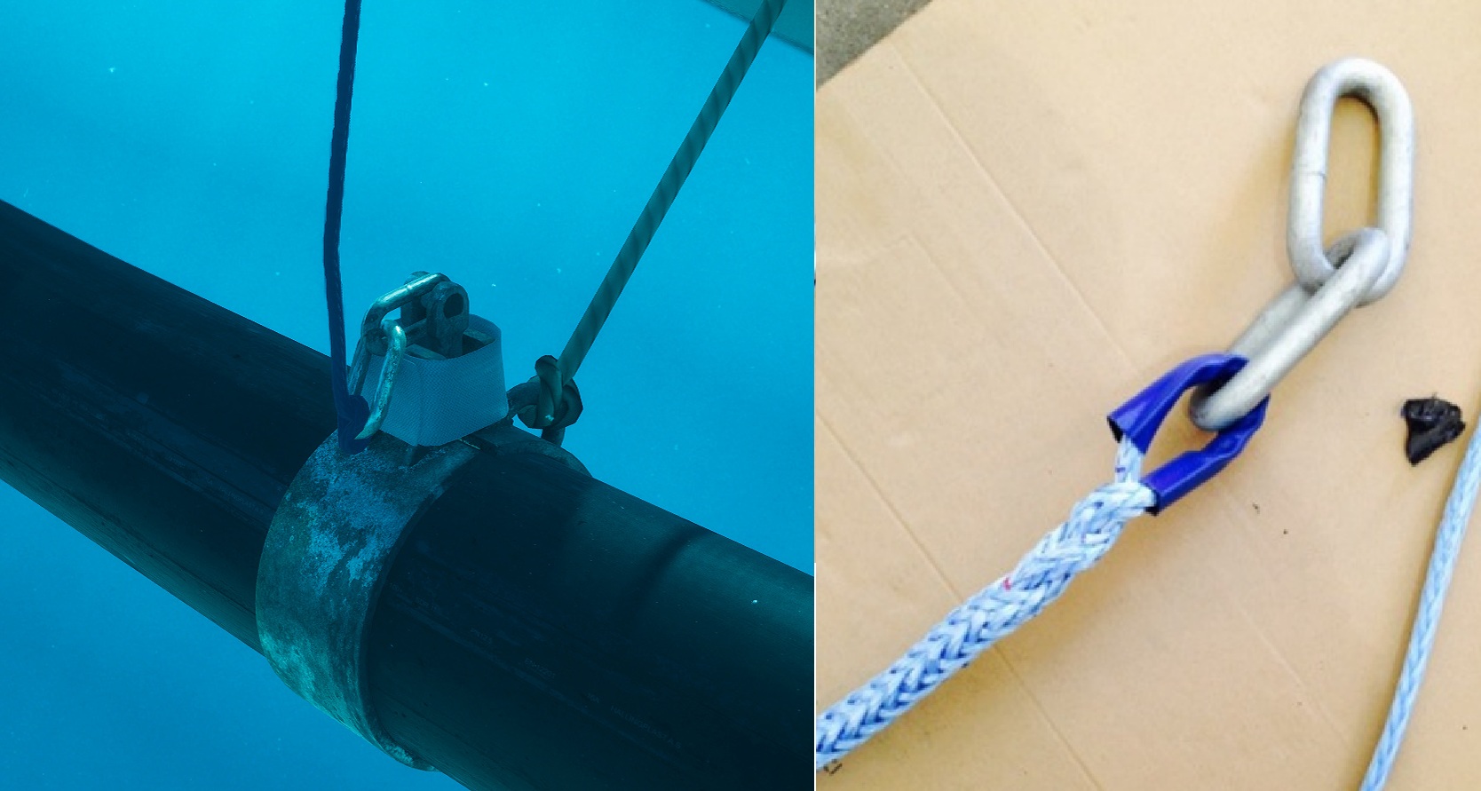
For sinker tube brackets, the winch rope must be connected to the chain loops as shown in Figure 4.2 either by choking or splicing. For replacement/installation, contact ScaleAQ for the procedure for splicing winch rope to sinker tube brackets.
For a Y-strap, the winch rope must be choked to a Y-strap loop as shown in Figure 4.3.

4.4 Installing the connection cabinet
Midgard connection cabinets must at all times be mounted on the ScaleAQ power cabinet module at all times, see chapter 2.2.
ScaleAQ recommends an orange plastic cover for protection against weather and wind for a longer service life of the connection cabinet.
Midgard connection cabinets must be installed by ScaleAQ or personnel with expertise and training in Midgard winch systems.
4.5 Installing the control cabinet
Midgard control cabinets must at all times be mounted in an associated steel frame stand from ScaleAQ, see chapter 2.3.
Alternative solutions must be made in consultation with ScaleAQ.
Midgard control cabinets must be installed by ScaleAQ or personnel with expertise and training in Midgard winch systems.
5 Use
5.1 Loading direction of winch rope
The winch rope must always be mounted in the drum in accordance with 4.2.
The loading direction of the winch rope must always be in accordance with Figure 5.1. Incorrect loading direction can lead to damage to the winch and pen.

5.2 Load
The Midgard Winch System is designed and developed exclusively for raising and lowering sinker tube or net systems for ScaleAQ cage systems.
Midgard winches should not be used for static loading. After lowering or raising operations, the Midgard winches should be relieved of any static load.
Midgard winches must not be used for lifting, raising or lowering anything other than what is described in this user manual.
5.3 Preparation before use
- Control cabinets are positioned in a way that ensures the signal cables to reach the connection cabinet with sufficient slack.
- Control cabinets should NEVER be placed on the pen and/or hang freely from a crane.
- Signal cables are connected to the correct connector in the connection cabinet, see labelling on cabinets and cables.
- In the case of an old version of the control cabinet against a new connection cabinet, use adapter type 2, see Figure 2.20.
- For a new version of the control cabinet against an old connection cabinet, use adapter type 1 according to Figure 2.21.
- Connect the main power cable to the power outlet/generator.
- Make sure that the EMERGENCY STOP switch on the outside is not triggered.
- For old version control cabinets, press the RESET button (Blue switch) on the outside of the cabinet to activate the cabinet.
- Use the rotary switch to choose between local or remote control.
- For local control of winches, activate rocker switches on the outside of the control cabinet for the winches to be operated.
- When using remote control, all rocker switches on the outside of the control cabinet must be deactivated on the old version.
- When using remote control, activate remote control.
See separate user manual for remote control. This must be available in a physical version inside the control cabinet. Contact ScaleAQ for a digital version.
The winches are now ready for use.
5.4 Lowering the sinker tube with winches
- The net is installed according to the user manual Nets (NYTEK23).
- The sinker tube is lowered by using all winches to avoid uneven loads in the sinker tube and on the winches.
- Ensure that the netting is not prevented from sinking freely during lowering.
- Lower the sinker tube until slack appears in all winch ropes.
- There must be a minimum of 70cm slack on the winch rope when the sinker tube is in the operating position.
- Manual suspension for the sinker tube between winches is adjusted to have a corresponding slack of at least 70cm.
- It is important to ensure the day after lowering that there is still 70cm slack in both the winch and manual suspension. This is due to drift and sea currents during the lowering operation.
The sinker tube is now fully submerged.
5.5 Raising the sinker tube with winches
- Prepare for the use of winches according to section 5.3.
- Start lifting with all winches to avoid uneven load on the sinker tube and winch system.
- Ensure that the netting does not become trapped during lifting. If necessary, take breaks in the lifting process to remove slack netting.
- When the sinker tube approaches the floating collar, the operator must ensure that the sinker tube is not raised higher than 1 m below the floating collar or that the winch rope comes into contact with the steel rod system. Stop / deactivate individually between the winches in the event of any unevenness.
- Finally, the winches should be relieved by tightening the manual suspension and ensuring that the winch rope has a minimum of 70cm slack.
Raising of the bottom ring is now complete.
5.6 Disconnection after use
- Press the EMERGENCY STOP switch on the outside of the main cabinet.
- Disconnect signal cables from the control connection on the pen. Ensure that all lids and hatches in the connection cabinet are closed.
- Ensure that the lids on the signalling cables are closed. The connectors on the signalling cables must not be allowed to fall into the sea or be subjected to other immersion in water.
- Disconnect main power.
- Store the control cabinet with associated cables and remote control. It is important that the control cabinet is stored indoors and connected to the main power supply. This is because the control cabinet is equipped with a heating element and thermostat.
5.7 Remote control
Start-up procedure:
- Set the rotary switch on the cabinet door to “Remote”
- Activate remote control (See Figure 2.17)
Remote control and Reciever are now paired.
Remote control switches itself off (Auto-CUT-OFF) after the set time (5, 10 or 30 min).
Each rocker switch activates its own winch. The rocker switch for “Up and Down” controls the activated winches. Switches for operating the winch in the cabinet door do not work in remote mode and vice versa.
After use, the emergency stop switch on the remote control can be used to switch it off.
The remote control should be stored in a dry place when not in use. Remote control should be charged regularly (approx. once a week), after a low battery warning, the unit should be able to operate for 60 minutes without problems. It is recommended to establish a fixed charging point indoors. The remote control can be left in the charging dock for a longer period of time without this having a major impact on its service life.
5.8 Additional key points when using the Midgard Winch
5.8.1 Transport brace
It is permitted to remove the transport brace once the winch is mounted to the winch bracket if necessary during lifting the winch rope with slings or similar. However, it is recommended that the transport brace remain mounted at all times to prevent relative movement between the gear box and the drum. If the transport brace is removed, associated bolts must then be stored, as they must be refitted when the winch is dismantled or serviced.

5.8.2 Avoid contact between winch rope and steel rod system
During raising and lowering operations, the sinker tube must not be raised to a level where the winch rope can touch the floating collar’s rod system under high load. This can damage both the rod system and the winch rope. The guideline height for raising the sinker tube is a maximum of 1 m below the floating collar, but this will vary depending on the circumference of the sinker tube and weather conditions during the raising operation. Operators must monitor contact between the winch rope and rod system when raising the sinker tube.


5.8.3 Replacing the winch rope
When replacing the winch rope, follow the instructions in 4.2 Mounting the winch rope on the drum.
6 Inspection and maintenance
6.1 Program for inspection and maintenance
To maintain the functionality and longest possible service life of Midgard Winch Systems, the following inspection and maintenance program should be followed.
In the event of a deviation, contact ScaleAQ service on tel. +47 488 52 488 and enter the number 2.
| Component | Description inspection / maintenance | Before / after operation | Monthly | Every 4 years |
| Winches | Close visual inspection for damage and corrosion. Check that all bolts between winch and bracket are intact. | X | X | |
| Winch rope | Close visual inspection of chafing and that the winch rope is intact. If minimum one strand is broken, the rope must be replaced. Check the slack in the winch rope after each operation. | X | ||
| Cabling and splice connectors | Check that all connectors and cables are undamaged and have sufficient slack. Ensure that cables are not in contact with elements such as transport protection over drums, walkways, etc. | X | X | |
| Cabinets | Check that the connection cabinet and control cabinet are undamaged and that connectors, cables and switches are intact. | X | X | |
| Winches | All winches are operated for a few seconds to lubricate components. This is to prevent wear and tear and maintain service life. | X | ||
| Handrail lock | Check that the handrail lock is intact and without damage/defects. | X | ||
| Connectors | Check that all connectors are intact and undamaged. Apply a thin layer of Molykote 4 to all connector housings. If there is a lot of residual lubrication in the connectors, remove it with compressed air before re-lubricating. | X | ||
| Winches | Recommended service interval at ScaleAQ indoor service. ScaleAQ’s experience indicates a 30% increase in service life if Midgard winches are serviced every 4 years for replacement of oil, seals and other components. | X |
6.2 Lifetime and replacement of winch rope
The service life of winch ropes depends on conditions of use, dimensions, load stress and UV exposure. The recommended replacement interval for winch ropes is every 2nd generation.
Beyond this, the following replacement criteria apply:
- Visible damage: In case of breakage of minimum 1 strand.
- UV damage: Obvious discolouration, fading or when the rope is hard/brittle.
7 Transport and storage
7.1 Instructions for lifting
The Midgard winch must be lifted using lifting straps as illustrated in Figure 7.1. It is important to find the centre of mass of the winch when lifting and that the ratio between the straps corresponds to the length ratio described below.
⚠️ Do not lift by the transport brace, as this may damage the winch.
Strap 1: Length from underside of hook to underside of electric motor is approx. 820mm.
Strap 2: Length from underside of hook to top of drum is approx. 1200mm.

7.2 Storage
Midgard Winches must not be covered with tarpaulins/covers or similar on site. This can create a corrosive environment and reduce the service life of the winch’s components.
When stored on land, the Midgard Winch must be stored in a dry place with good access to oxygen to avoid corrosion and reduced component life.
8 Manufacturer and product identification
| HEAD OFFICE | |
| Scale Aquaculture AS | Tel: +47 73 80 99 30 |
| Beddingen 16 | E-mail: post@scaleaq.com |
| 7042 Trondheim, Norway | www.scaleaq.com |
| CONTACT INFORMATION | |
| ScaleAQ Service | Tel: +47 488 52 488 (dial the number 2) |
| Lars Andreas Larsen, Product owner Midgard Winch | Tel: +47 995 45 742 E-mail: lars.andreas.larsen@scaleaq.com |
| Petter Stangvik, Service technician | Tel: +47 994 86 785 E-mail: petter.stangvik@scaleaq.com |
8.1 Identification Midgard Winch
All Midgard winches have an ID tag with a serial number attached to the gear housing as illustrated in Figure 8.1.
Midgard Winch version 1.0 has serial numbers up to and including 18041, and 18192 to 18626.
Midgard Winch version 1.1 has serial numbers from 18042-18191, as well as 18627 and out.

8.2 Identification Midgard connection cabinets
Midgard connection cabinets are labelled with a serial number on the front of the cabinet as shown in the example in Figure 8.2.

8.3 Identification Midgard control cabinet
Midgard control cabinets are labelled with a serial number on the front of the cabinet as shown in the example in Figure 8.3.

9 Revision history
| Rev. | Changes | Date |
| 1 | Text and figures/images revised in their entirety. | 24.08.2018 |
| 2 | User manual updated in its entirety in accordance with NS 9415:2021 and NYTEK23. Updated with Midgard Winch 1.1 and latest version of control cabinet w/remote control, junction box and adapters. | 19.03.2025 |
| 3 | Added Rope guide in chapter 2.1.6. Updated chapter 6 Inspection and maintenance. | 27.05.2025 |
10 References
| /1/ | NYTEK23 |
| /2/ | NS9415:2021 |