Manuals
Pen – FrøyaRingen (NYTEK23)
Important information is marked with the following symbols:

1. Summary with an overview of the component and key points related to escape prevention
1.1 General definitions
| Aquaculture farm | Installation for the farming of fish. |
| Basin dimensions | The pen’s inner circumference. |
| Design working life | Assumed period for which a structure or part of it is to be used for its intended purpose with anticipated maintenance but without major repair being necessary. |
| Operation | Fish farming at site, including all installation and operation activities performed at the site while fish farming is in progress, and that are of relevance to the escape prevention of fish. |
| Extra equipment | Equipment that is not a main component. |
| Inspection | Systematic inspection/examination, usually visual, to ensure that the equipment satisfies the requirements. |
| Floater | Structure whose main function is to provide an enclosure with buoyancy and/or stiffness. |
| Anchoring system | System of lines and bottom attachments with the main function of keeping the aquaculture farm or raft in position. |
| Bridles | Anchoring line between the floater and the anchoring system. |
| Main component | Part of an aquaculture farm that holds one or more of the installation’s load bearing main functions. Example: Floater, anchoring system, raft and enclosure. |
| Enclosure | Net or other system of load bearing parts that form a barrier between the farming volume in a production unit and the surrounding water volume. |
| Bracket | Component keeping the inner and outer floating collar pipes together. |
| Weight | Weight or other device attached to the net to achieve the intended shape. Centre weight is attached beneath the bottom centre of the net-cone. |
| Cage | Floater with enclosure. |
| NS9415:2021 | Standard which sets out functional requirements for floating aquaculture farms and will be fundamental for stakeholders in the aquaculture industry, such as authorities, supervisory bodies, designers, suppliers, actors within R&D and manufacturers, as well as aquaculture farm owners. |
| NYTEK23-regulation | Governing Regulation for Fish Farming in Norway. |
| Circumference | Inner length of the inner floating collar. |
| Product certificate | Document confirming that the net is produced in accordance with requirements in NYTEK23 and NS9415:2021. |
| Suspension system | Weight, sinker tube or similar used to keep the three-dimensional shape of the net. |
| Load bearing system | Framework consisting of steel rods and chains connecting all the brackets on the floating collar, which ensures structural integrity of the pen and distribution of the forces acting on the pen to the entire structure. |
1.2 Introduction
This user manual applies to ScaleAQ fish farming pens delivered within the requirements for NS9415:2021 and NYTEK23.
The guiding principle behind our success has been the combination of the flexibility of high density polyethylene pipes and central steel rib, with the focus on the interaction between the moorings and pen to spread the strain throughout the entire structure. A major design feature of our pens is the integrated load bearing system.
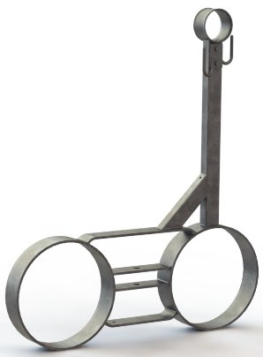
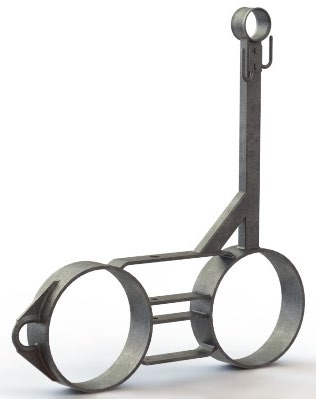
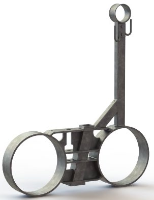
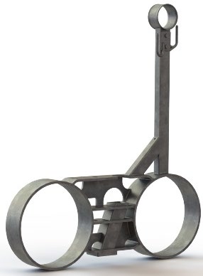
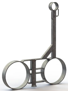
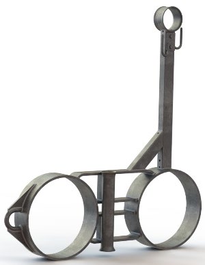
2. Description of the pen and its components
The construction consists of the following:
- Double floating collars and handrail made of polyethylene plastic.
- Welded steel brackets or injection moulded plastic brackets threaded on the floating collars.
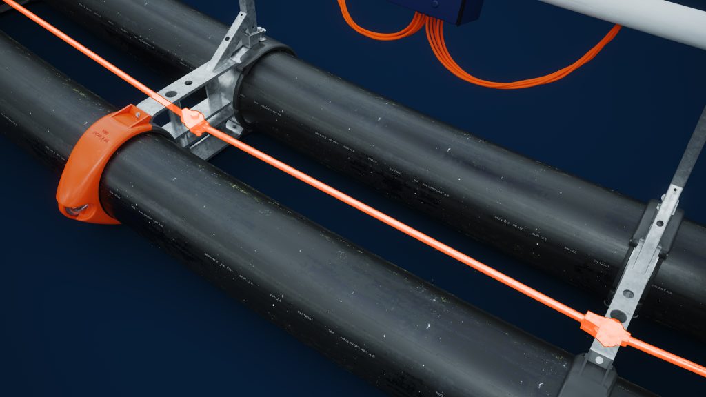
- Brackets are anchored by a dimensioning load bearing system in the horizontal plane visualised in Figure 2. In the load bearing system, steel braces/chains/fibre ropes connect the brackets and distribute the load throughout the circumference of the pen.
- Mooring brackets made of steel take the strain from the mooring system which is further distributed to the entire circumference due to this structure.
- The capacity of the steel brackets allows torque and load on handrail posts and maximum loads on the suspension system are all listed in the product certificate of the pen.
- The distribution of the mooring brackets prevents ovalization of the floating collars. Hence, local buckling is prevented and the flexibility of the floating collars is maintained.
- Installation of the net at the bottom of the handrail posts ensures load distribution in the entire structure.
- Bushings between steel brackets and floating collar pipes reduce the friction. The floating collars have free motion inside the brackets, both rotationally and horizontally.
- For the pens having a sinker tube, this component needs brackets adapted for this purpose.
- Styrofoam rod segments are inserted inside the floating collar pipes to ensure the buoyancy if the floating collar pipes are damaged or punctured.
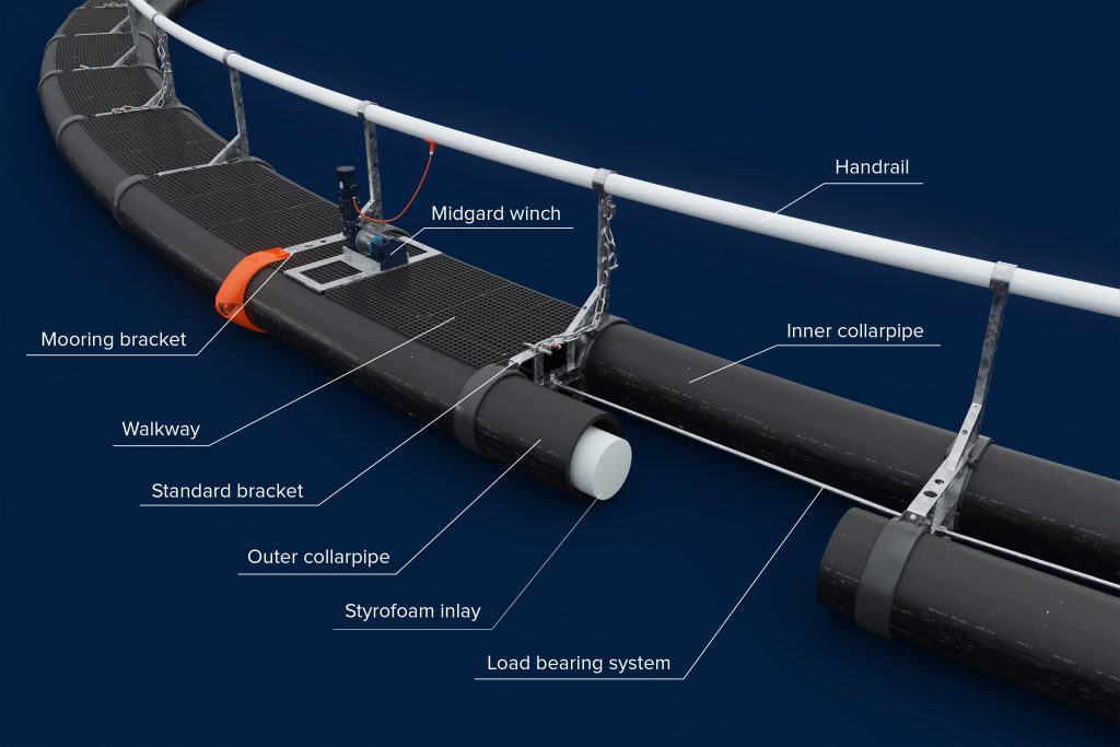
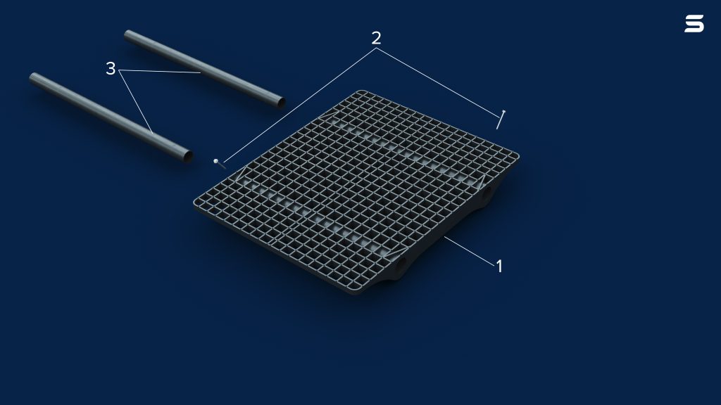
- Walkway grate
- Walkway screw
- Walkway pipe
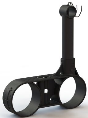
2.1 Types of brackets
The variety of brackets are illustrated in Figure 4.
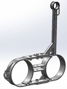
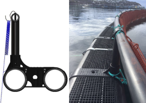
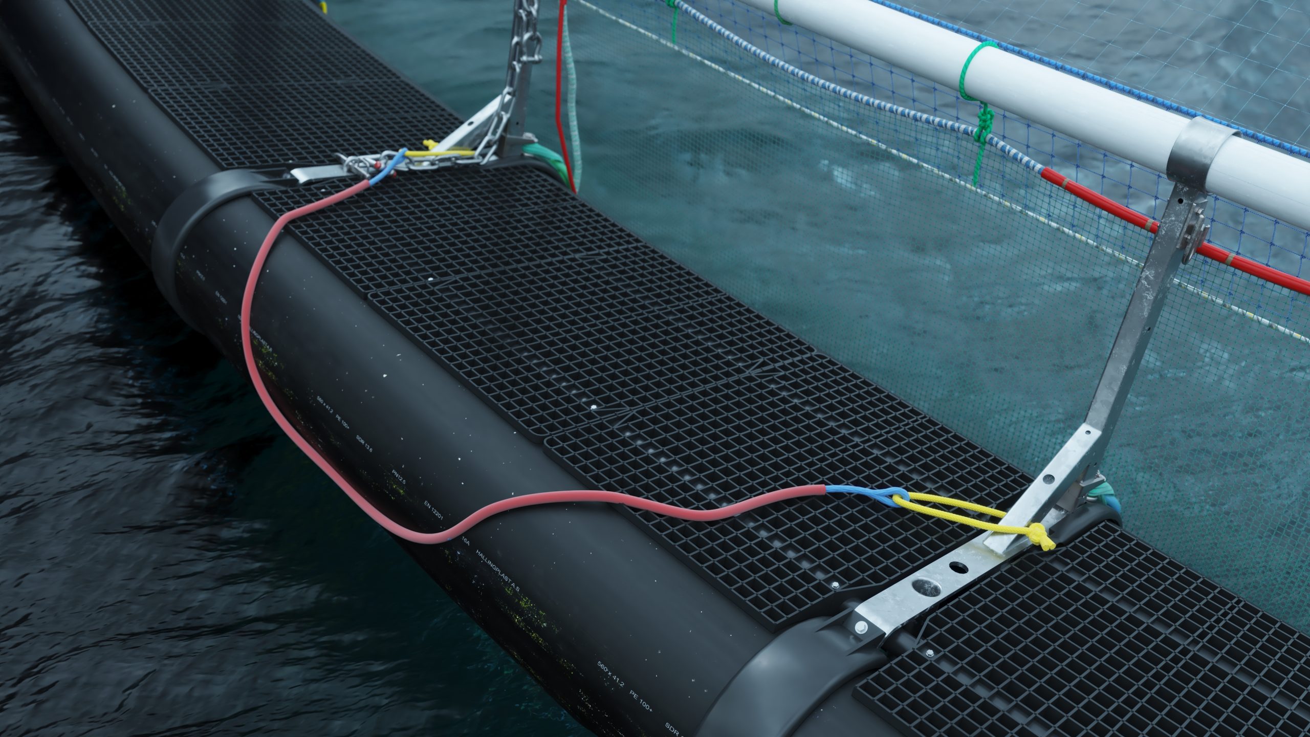
Components of a mooring bracket are illustrated in Figure 5.
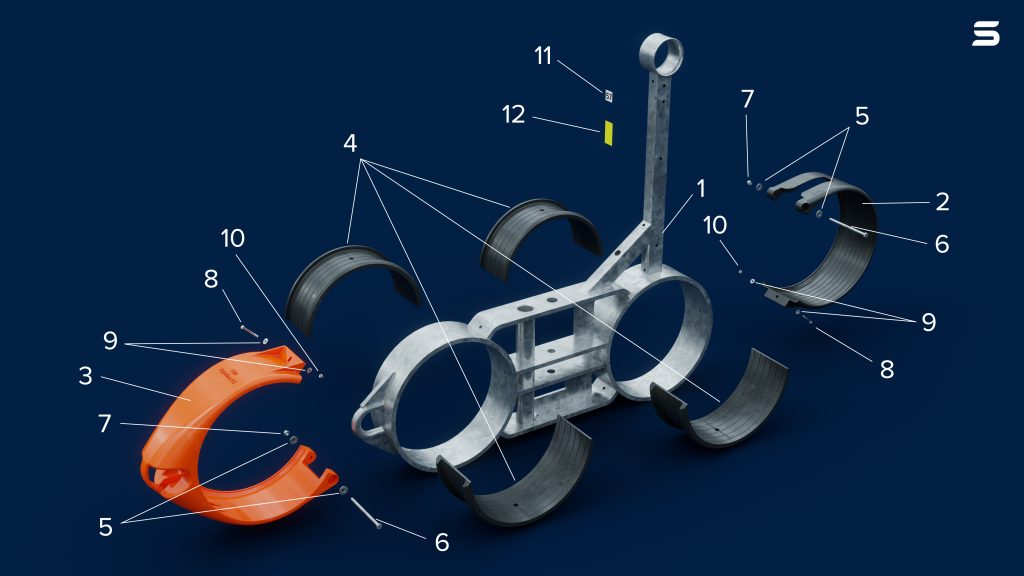
- Mooring bracket in galvanized steel
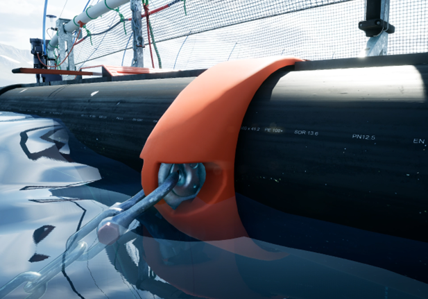
- Inner fender
- Outer fender mooring clamp
- Bushing
- Washer
- Bolt
- Nut
- Bolt
- Washer
- Nut
- Bracket numbering sticker
- Reflective sticker – yellow for outer mooring bridles, red for inner bridles
2.2 Steel rods in the load bearing system
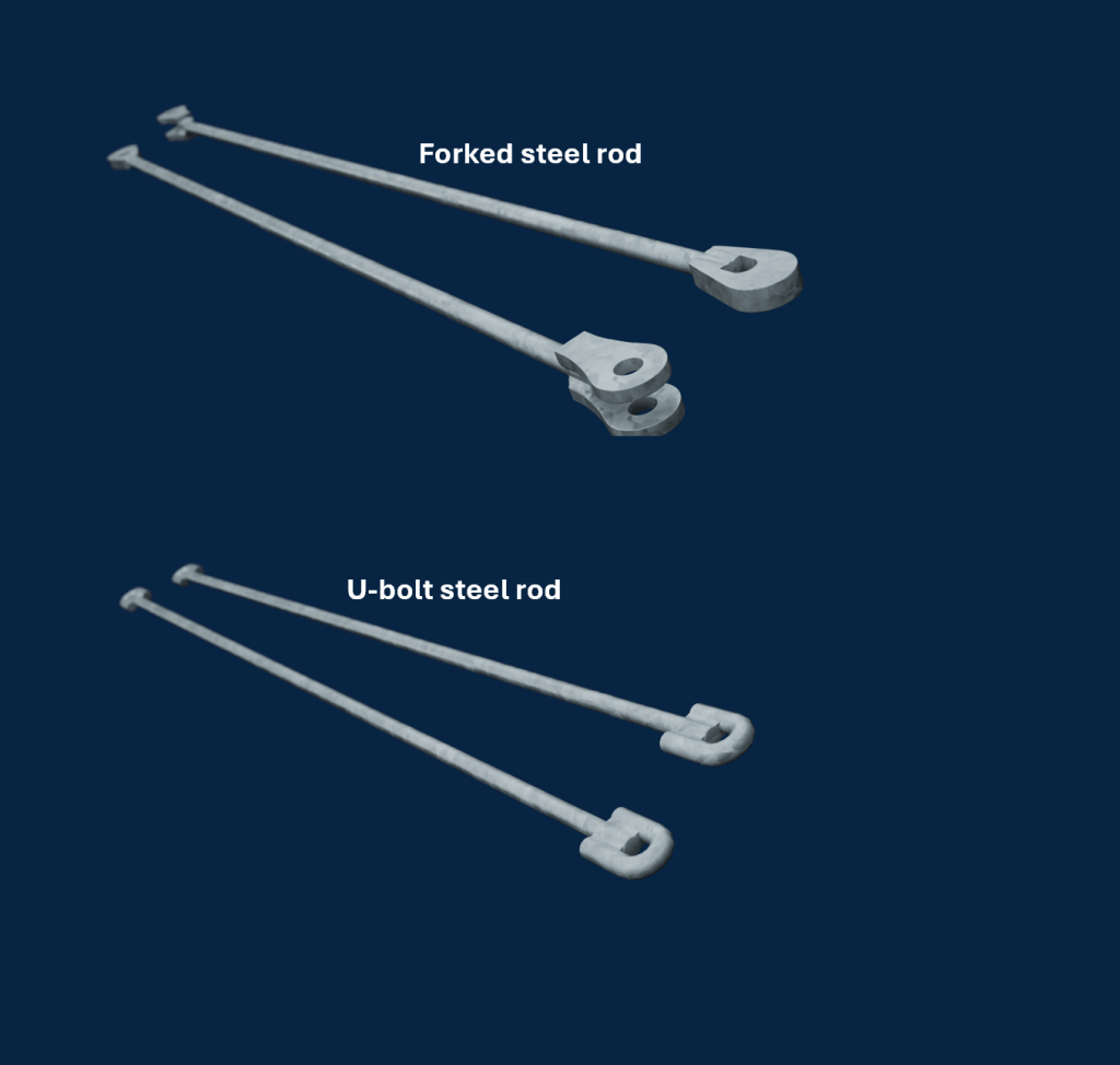
The steel rods distributing the load are illustrated in Figure 6.
2.2.1 Types of steel rods
Types of steel rods supplied by ScaleAQ as illustrated in Figure 7.
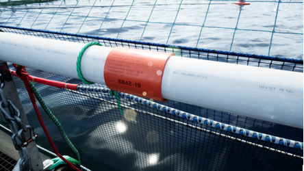
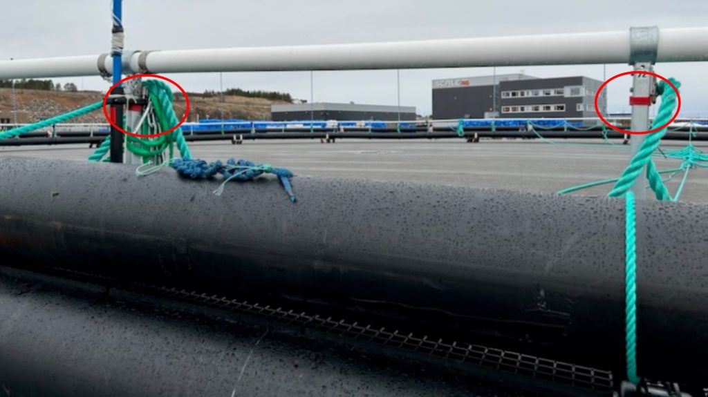
2.3 Marking of the pen
Each pen will have its individual serial number identifying the products. The pen is marked with a unique red ID-marker tube in plastic, mounted on the handrail where the security chain is located. If the ID-marker is replaced, the new marker must be mounted at the exact same location on the pen.
Another important marking on the pen is the red band attached to the two steel brackets shown in Figure 9 indicating where the sinker tube has its last butt fusion welding between these two brackets.
2.4 Net buoyancy for the pen
The product certificate describes the net buoyancy of the pen without any extra equipment like the sinker tube.
2.5 Specifications for the pen
| 315 | 400 | 450 | 500 | 560 | 630 | |
| Circumference* | 60-120 m | 80-160 m | 90-180 m | 120-200 m | 120-200 m | 140-++ m |
| Diameters* | 19,1-38,2 m | 28,6-50,9 m | 28,6-57,3 m | 38,2-63,7 m | 38,2-63,7 m | 44,6-++ m |
| Surface | 286-1146 m2 | 509-2037 m2 | 945-2578 m2 | 1146-3183 m2 | 1146-3183 m2 | 1560-++ m2 |
| Floating collar | Ø 315 mm | Ø 400 mm | Ø 450 mm | Ø 500 mm | Ø 560 mm | Ø 630 mm |
| Handrail | Ø 125 mm | Ø 140 mm | Ø 140 mm | Ø 140 mm | Ø 140 mm/ **Ø 160 mm | Ø 160 mm |
| Styrofoam | In both floating collar pipes | In both floating collar pipes | In both floating collar pipes | In both floating collar pipes | In both floating collar pipes | In both floating collar pipes |
| Mooring brackets in steel | Standard | Standard | Standard | Standard | Standard | Standard |
| Plastic bushings | Standard | Standard | Standard | Standard | Standard | Standard |
| Fenders | Standard | Standard | Standard | Standard | Standard | Standard |
* Circumference and diameter are measured inside the inner floating collar.
**For pen with plastic brackets.
2.6 Prerequisites and limitations

There is a prerequisite that equipment and components approved by ScaleAQ AS are used when doing replacements of such parts on the pen. ScaleAQ has responsibility only when spare parts and service personnel approved by ScaleAQ are used. The ID-marker on the pen can be used as a point of reference when it comes to controlling where inspection and maintenance is being conducted on the pen.
2.7 Unwanted events
2.7.1 Breakage or damage to the floating collar

If the floating collar gets damaged or breaks, the structure will keep its shape and prevent total breakdown. The brackets connected by a load bearing system in the horizontal plane will maintain the structure. ScaleAQ FrøyaRingen pens are delivered with floating collars filled with rods of styrofoam. The mission of these rods is to maintain buoyancy if the floating collar gets damaged or punctured. If both floating collars get punctured, net buoyancy is reduced by the numbers listed in Table 3.
| Dimension floating collar [mm] | Reduction of net buoyancy if both floating collars get punctured |
| 315 | 9% |
| 400 | 4% |
| 450 | 28% |
| 500 | 39% |
| 560 | 50% |
| 630 | 60% |
2.7.2 Tide variations and storm tide
Tide variations and storm tide are not critical elements for the performance of the pen.
2.7.3 Ice and snow
Ice and snow can cause severe loads to the pen structure. The effect of ice formation is primary linked to the loss of buoyancy. Ice and snow should be removed preferably by using a wooden or rubber sledgehammer in rubber or wood. The rope used for tightening the bird net to the floating collar should have low breaking force. In the event of heavy ice formation on the bird net, the ropes will break, and the bird net will fall into the water causing the ice to melt.
Fish farming localities exposed to ice formation and drift ice must have contigency plans and action plans for removal of ice.
2.7.4 Handling of dead fish
In order to get the best functional handling of dead fish, it is of high importance that the net has a correct attachment to the floating collar and has a proper suspension. If this is fulfilled, the net and the bottom especially have no folds or coiling in the ropes and netting. The dead fish will then be possible to collect from the bottom center of the net.
The fish farmer must have good routines for the surveillance of the fish and dead fish removal. The frequency of dead fish removal is daily.
2.7.4.1 Critical number of dead fish
Prerequisites:
- The weight of the dead fish is evenly distributed in the bottom of the net.
- The weight of the dead fish beneath the surface is 10% of the weight in air.
In order to calculate the capacity of critical number of dead fish, the “critical number of dead fish per cross rope in the net” is multiplied by half of the number of cross ropes in the net. The number of cross ropes and dimension of the cross ropes can be found in the net certificate and the sketch of the net.
For example:
- Number of cross ropes: 20 pcs.
- Dimension cross ropes: 30 mm.
Critical amount of dead fish = 10 pcs cross ropes x 3 050 kg = 30 500 kg. This is the weight in the sea. The weight in air is calculated by:
30 500 kg x 10 = 305 000 kg.
The critical number of dead fish must not exceed the residual buoyancy of the pen. Net buoyancy of the pen without extra equipment like sinker tube is documented in the pen certificate.
3. Interface with other components
The pen is engineered for interacting with other main components and extra equipment. The supplier of main components and extra equipment must engineer their equipment in accordance with the specific pen.
3.1 Interface with the net
Pens supplied by ScaleAQ are engineered to document the interface with the relevant net. The pen certificate presents important information about this interface and the user limits for the pen together with the weight and suspension system.
3.2 Interface with the suspension system
Pens supplied by ScaleAQ are engineered to document the interface with the weight and suspension system. The pen certificate presents important information about this interface and the user limits for the pen together with the weight and suspension system.
3.2.1 Suspension system with sinker tube
ScaleAQ FrøyaRingen pen can be delivered with sinker tube. For more information, read the user manual for suspension system with sinker tube.
3.2.2 Suspension system with bottom weight
By using bottom weight as suspension system for the net, the total weight of the bottom weight must not exceed the similar total weight for the sinker tube for the specific floating collar. The weight of each bottom weight cannot exceed the corresponding weight of each sinker tube suspension. Allowed sinker tube weight is documented in the product certificate for the specific pen.
3.2.3 Pointed weight
The pointed weight is an integrated part of the net. There are no other weights, and it has its function in the bottom point of the net. In order to be sure of the correct use, relevant conditions given by the net supplier that apply to the use of weights should be checked. Net is a main component of the pen that must be certified in accordance with NS-9415. The use of extra equipment must be described in the net user manual.
3.3 Interface with permanent extra equipment
When using permanent extra equipment on the pen affecting integrity and the performance of the pen, ScaleAQ must be contacted for guidance and approval.
3.4 Interface with temporary extra equipment
When using temporary extra equipment on the pen affecting integrity and the response of the pen, ScaleAQ must be contacted for guidance and approval.
4. Assembly of the pen
The ScaleAQ pen is already assembled upon delivery. Assembling of the ScaleAQ pen is conducted by certified assemblers keeping the status as assembly leader through training and qualification. The assembly leader is approved and appointed by the assembly manager in ScaleAQ. All welders and assemblers have documented competency for assembling the ScaleAQ pen.
5. Installation on site
Installation together with other components must be carried out in accordance with requirements in other components’ user manuals and/or product certificates. There must be requirements related to how other components are installed with the mooring system. Two important risk factors are: staying below the capacity limits of other components and securing that the attachment between other components and the mooring system is not introducing any wrong loads to other components or the mooring system which could lead to capacity reduction.
Prior to installation at site, a safe job analysis (SJA) must be conducted.
5.1 Installation of pen in the mooring frame
Bridles in the mooring system are attached to the mooring brackets on the pen.
- All bridles must keep identical rope/chain type and dimension.
- The pen should be centrally oriented in the mooring frame.
- Pre-tension: Pre-tension forces must be distributed in the mooring system and not in the bridles.
- All shackles used for mooring of the pen must be secured with plastic-coated galvanized steel wire or similar material not causing corrosion. DO NOT use splinters of stainless material. Installation of mooring lug insert is highly recommended as this is easy to replace when worn out.
- Without mooring lug insert, the shackle must be attached by the hoop in the mooring lug and bolt in the chain.
- When having a mooring lug insert, the shackle can be installed both with hoop and bolt in the mooring lug insert.
Maximum allowed payload for mooring attachment point is documented in the product certificate.
It is assumed that the mooring system is dimensioned for the similar or higher allowance for significant wave height and current.
5.2 Recommended frame size in mooring system
For ScaleAQ pens it is recommended to follow minimum frame size specified in Table 4 for the various pen circumferences.
Table 4 is based on the pen being installed in accordance with information given in Section 5 and 5.1.
| Circumference pen [m] | Minimum frame size [m] |
| 90-100 | 55×55 |
| 120 | 65×65 |
| 135/140 | 70×70 |
| 157/160 | 80×80 |
| 200 | 100×100 |
For pen circumferences or frame sizes deviating from the recommendations in Table 4, contact ScaleAQ for consultancy and check of integrity between pen, net and mooring system.
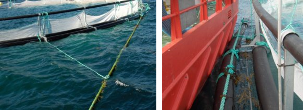
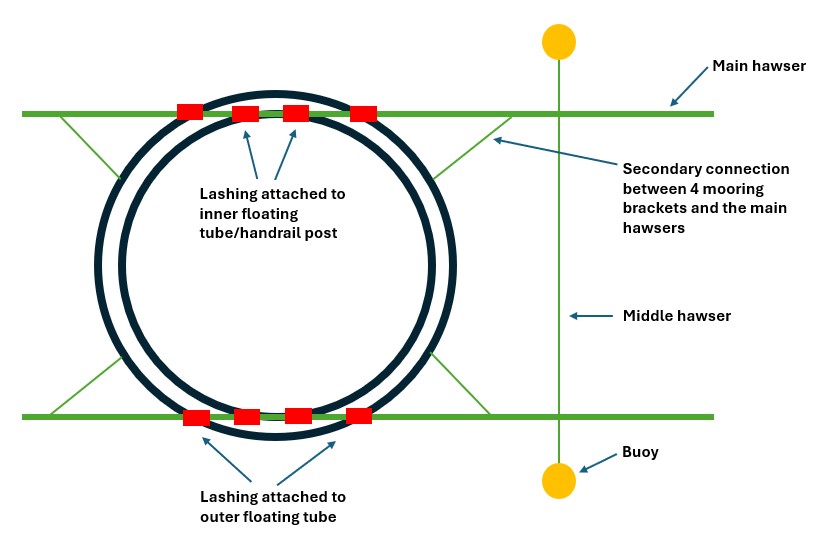
5.3 Installation of pen in ladder anchoring
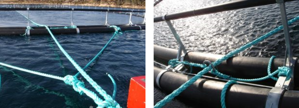
Another mooring system is the ladder anchoring where the pen is connected to 2 main hawsers. Minimum 4 lashings must be used at each side of the floating collar. The lashings can be attached to both the inner and outer pipe of the floating collar. If attaching to the inner pipe, the lashing can be tightened to the lower part of the handrail post. It is also recommended to have a secondary connection between the mooring bracket and the main hawsers by ropes.
It is of high importance to regurarly control the anchoring system when it comes to the risk of tearing in the contact point between rope and walkway, and between rope and service vessel. A measure reducing the risk of rope tearing can be to protect the rope by padding.
5.3 Installation of net
The net must be adapted to the pen. Installation must follow specifications from the net supplier.
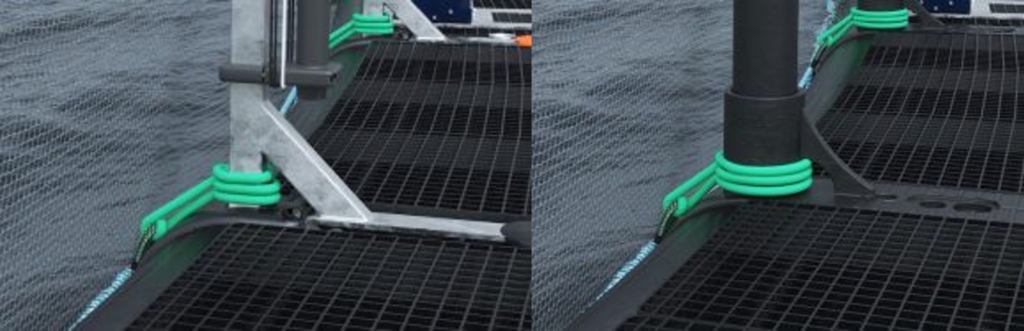
When attaching the net to the pen’s handrail posts, it is important that the ropes are attached at the bottom part of the handrail posts in order to prevent any vertical movement of the ropes in case of heeling of the pen which could lead to unwanted loads on the pen. When using sinker tube, read the user manual for more information about this. ScaleAQ supplies injection molded net hook protector as extra equipment which simplifies net handling.
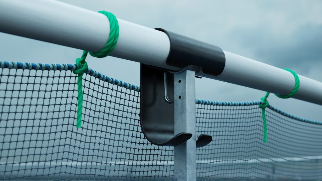
Alternatives for attaching the net to the pen’s handrail posts are visualised in Figure 16-19:
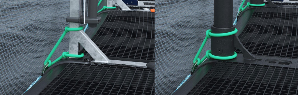
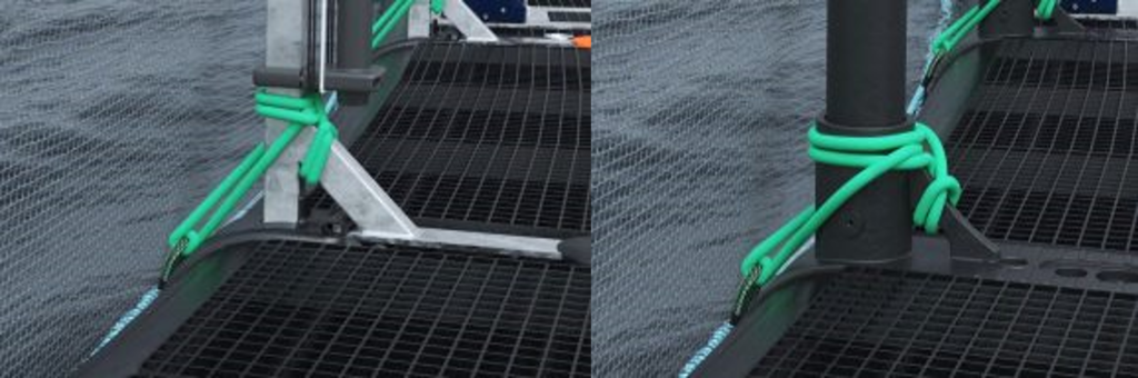
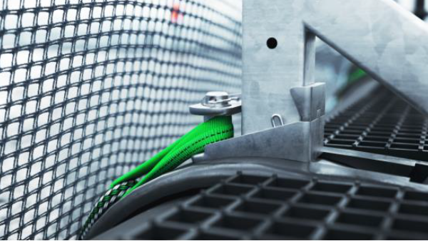
5.4 Attachment of lifting rope from the waistline in the net to the pen for nets designed for this
The attachment point for lifting rope from e.g. ScaleAQ Midgard® Net is between the pipes on the chain-brackets adapted for this type of attachment. See Figure 20. Loops on the main rope are attached with a combination of strap and chain segment.
- When using sinker tube, all the net attachments to the pen must be fastened before lowering the sinker tube.
- The jump net is not supposed to be attached to the net hooks during operation.
5.5 Combi net
In order to avoid heavy loads on the handrail and tearing of net, no more than 5m of netting should be lifted per attachment point per round (around the pen). During suspension of the net, the operator must make sure there is no part of the net being connected to the handrail as this can result in breakage of the net mesh. In periods with risk of icing, risk reducing measures must be conducted if the combi net is going to remain suspended. One example of a risk-reducing measure is the use of an ice-skirt.
6. Use
6.1 Use and securement of chains, ropes and cables
Chains, ropes and cables must be used and secured in a proper way to make sure they will not cause any damage to the pen, net, anchoring and extra equipment. It is of high importance that the chains, ropes or cables are NOT hanging between the floating pipes and causing damage to the load bearing structure of steel rods/chains.
6.2 Mooring of vessels
6.2.1 Mooring of service vessels
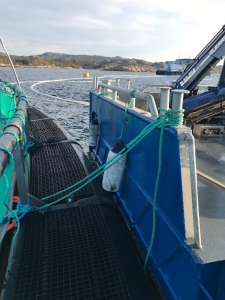
Workboats and well-boats must be moored to the pen in a way that is not risking any damage to the net, anchoring or pen. Mooring in this setting is referred to as a temporary mooring related to work operations. Vessels can be moored to the bottom part of the brackets in the inclined bracket support. NO mooring to handrail posts, handrails, chains or steel rods.
6.2.2 Mooring of larger vessels and well-boats
When mooring larger vessels e.g. well-boats and service vessels, a special mooring method for large vessels should be used which is shown in Figure 23.
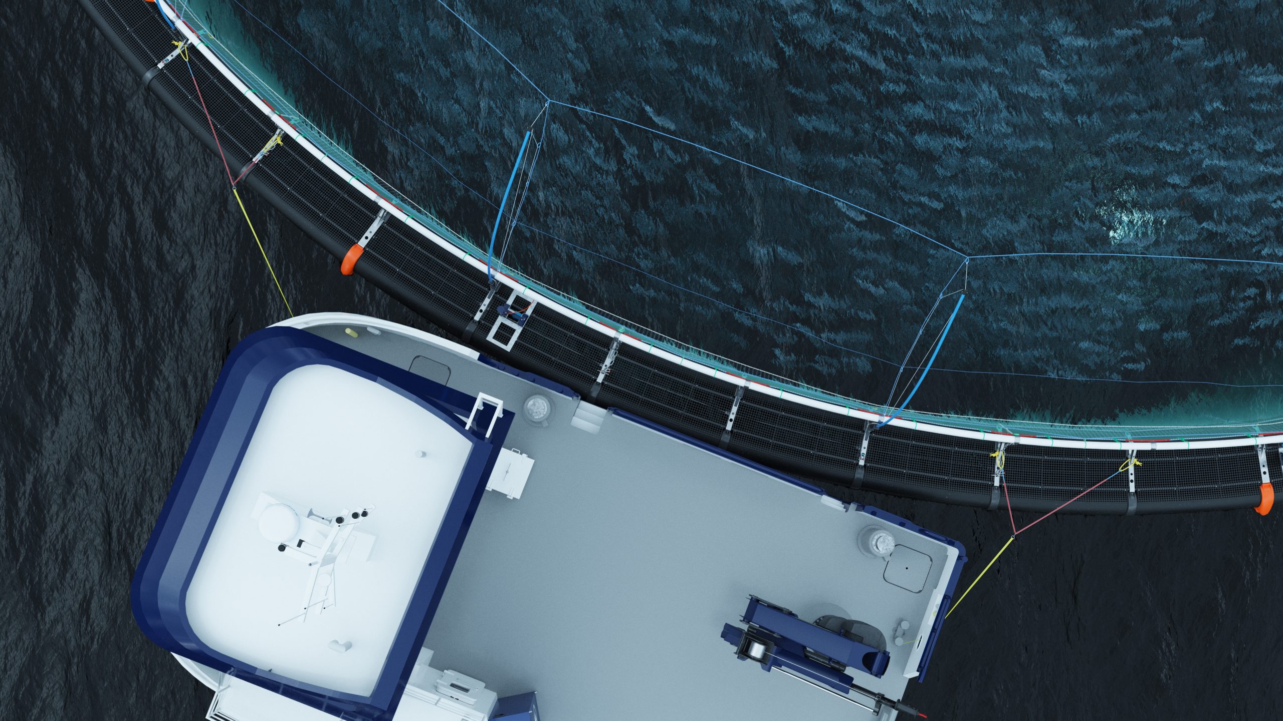
If the mooring method for large vessels is not available, it is possible to carefully secure the vessel to the mooring lugs on the middle bridle connected to the pen. If this is necessary, take into account that maximum allowed load is reduced when the angle towards the mooring lug deviates from 90°. See Figure 24.
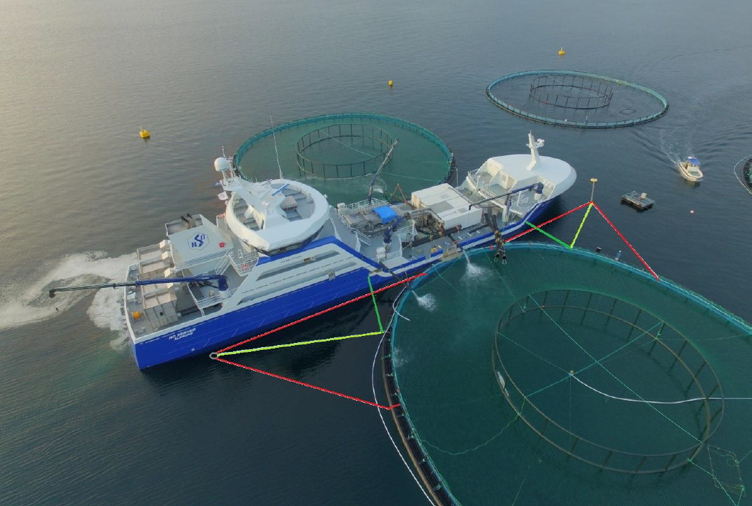
Maximum allowed load from mooring of vessel is shown in Table 5.
| Dim. floating collar | Max. allowed load from mooring of vessel [tons] in inclined bracket support | Max. allowed load from mooring of vessel [tons] in middle bridle |
| 315 | 6.7 | 12 |
| 400 | 6.7 | 15 |
| 450 | 7.7 | 15 |
| 500 | 7.7 | 15 |
| 560 | 7.7 | 25 |
| 630 | 9.7 | 25 |
Max. allowed load in middle bridle is based on load 90° to the pen. Max. allowed load is reduced the more the angle deviates from 90°.
6.3 Lifting of pen
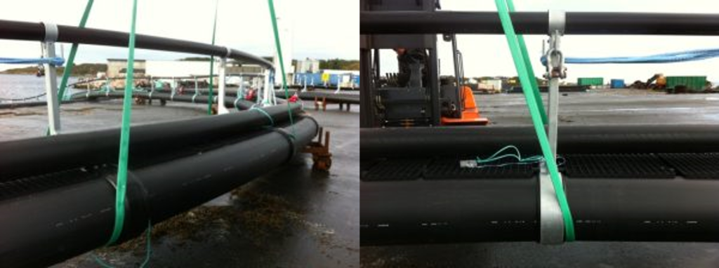
For lifting operations, it is recommended to use 2 pcs. of wide lifting straps ca. 3m from eachother to get 2 brackets between the lifting contact points. The straps must be placed around each of the pipes in the floating collar, not around the sinker tube. Work angle: β < 30°. (The angle between the strap and a vertical line). The maximum allowed lifting height from the water level is 3m.
| Dim. floating collar | Width of lifting strap [mm/ton WLL] |
| 315 | 90mm/3T |
| 400 | 90mm/3T |
| 450 | 120mm/4T |
| 500 | 120mm/4T |
| 560 | 150mm/5T |
| 630 | 150mm/5T |
6.4 Cleaning
After each production cycle it is normal to clean the pen and sinker tube if applicable. A flushing rig tailored for removing fouling and shells is normally used. If a crane is used instead, make sure that the pen is securely attached to the lifting straps and that nobody is located underneath suspended loads. When using disinfectants and other chemicals, be sure that the chemical used does not damage the pen’s components.
6.5 Precautions during launching and take-up of pen
Space requirements: The area must be sufficient for the pen and free passage around the pen of approximately 10m. When the pen is brought to land, cranes or other suitable lifting equipment can be used, ref. chapter 7.3. To lift the entire floating collar, large cranes are necessary, and this is not practical for floating collars having a circumference of 90m and larger. The most normal lifting method is a combination of lifting force and pull force.
It might be convenient to ovalize the pen during take-up, and this can be done by using ropes across the pen, forcing it into ovalization. Make sure that the pipes do not reach a too sharp bending ratio which could lead to breakage. (Maximum allowed decrease in diameter during handling is 15%.)
Do not transport equipment on top of the floating collar and make sure that sharp edges of machinery equipment are not damaging the pipes.
7 Inspection and maintenance
7.1 Precautions
When replacing equipment and components on a ScaleAQ pen, the new equipment and components must be approved by ScaleAQ AS. The responsibility lies with ScaleAQ only when spare parts and service personnel approved by ScaleAQ are employed.
The ID marker on the pen can be used as a point of reference when it comes to keeping control of which area the maintenance work is taking place on the pen and follow the number of brackets clockwise from the ID marker.
During normal operation, inspections and maintenance of the pen must be conducted regurarly. Based on risk evaluations and risk analysis performed by ScaleAQ, inspection and maintenance intervals with check points have been created and are minimum requirements during normal operation.
The owner of the pen must have an inspection and maintenance program where all details are documented and kept together with other documentation of the specific pen.
7.2 Inspection methods
- GVI = General visual inspection:
Visual inspection in which the inspector looks for obvious damages at a distance from the object. This can be performed with ROV or diver with a normal camera. - NVI = Near visual inspection:
Use of near vision camera or detection tool (e.g. ultrasound) to identify damage near the surface to the object. - DC = Dimension control:
Use of measuring tools to control dimensions. - MR = Modification / Replacement
7.3 Acceptance criteria for pen quality standards
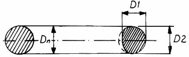
Pen component tolerances are listed in chapter 7.3.1-7.3.4. If these tolerances are exceeded, the pen does not satisfy quality standards and ScaleAQ must be contacted for a review. These chapters also describe the measure method where 2 diameters are measured (D1 and D2) 90 shifted relative to each other.
7.3.1 Tolerances for wear of rods, chains, bolts and shackles
Tolerances for wear of rods, chains, bolts and shackles: ≤ 20% of original material diameter (Table 6), measured over 2 diameters (D1 and D2) 90° shifted relative to each other. Hence, the remaining diameter (D1+D2)/2 needs to be minimum 80% of nominal diameter Dn.
| Type | Bolt in load bearing structure [mm] | Steel rod in load bearing structure [mm] | Chain in load bearing structure [mm] |
| 315 | M24x130 | 25 | 16 |
| 400 | M24x130 | 25 | 16 |
| 450 | M24x130 | 25 | 16 |
| 500 | M30x160 | 30 | 22 |
| 560 | M36x180 | 36 | 25 |
| 630 | M36x180 | 36 | 25 |
7.3.2 Tolerances for plastic pipes
If damages to plastic pipes are deeper than 20% of the wall thickness, ScaleAQ must be contacted for evaluation of repairs.
| Type | SDR | Pipe wall thickness [mm] | Max. damage depth [mm] |
| 315 | 21.0 17.6 | 15.00 17.89 | 3.0 3.6 |
| 400 | 17.6 | 22.72 | 4.5 |
| 450 | 21.0 17.6 13.6 | 21.43 25.56 33.09 | 4.3 5.1 6.6 |
| 500 | 17.6 17.0 13.6 | 28.41 29.41 36.76 | 5.7 5.9 7.4 |
| 560 | 17.6 17.0 13.6 | 31.82 32.94z 41.17 | 6.4 6.6 8.2 |
| 630 | 17.6 13.6 | 35.80 46.32 | 7.2 9.3 |
| Walkway pipes FR/FRPL315-FR/FRPL500: Ø50 mm | 50% | ||
| Walkway pipes FR/FRPL560-FR630: Ø63 mm | 50% |
7.3.3 Tolerances for mooring lug ear
Tolerances for wear of mooring lug ears: ≤25% of original material thickness (Table 8) measured over 2 diameters (D1 and D2) 90° shifted relative to each other. The remaining diameter (D1+D2)/2 must be minimum 75% of nominal diameter Dn.
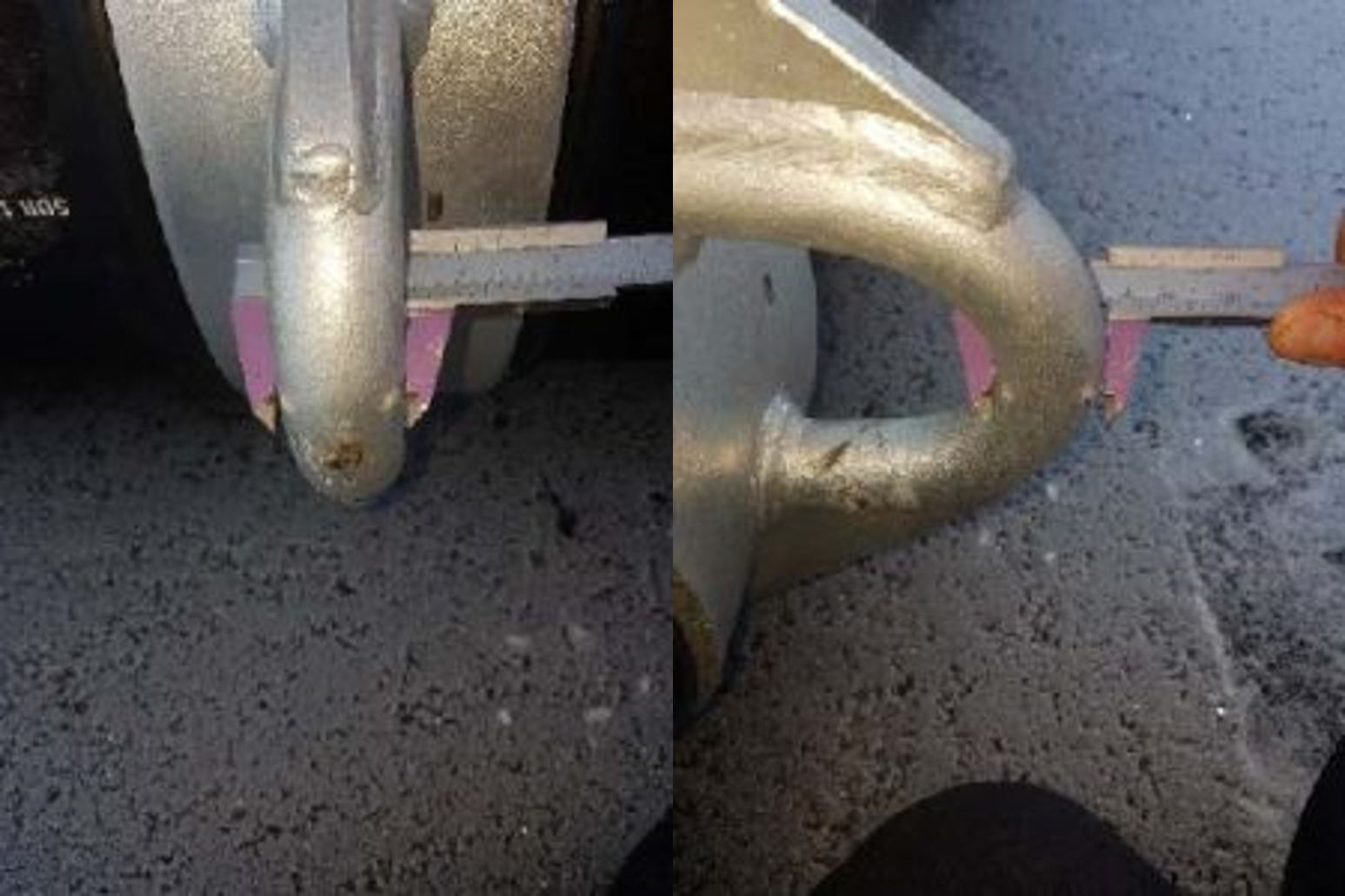
Normally during wear of mooring lug ears, the width of the ear remains the same and the reduced diameter is 90° shifted relative to this.
| Type | Mooring lug ear [mm] |
| 315 | 30 |
| 400 | 30 |
| 450 | 30 |
| 500 | 36 |
| 560 | 40 |
| 630 | 40 |
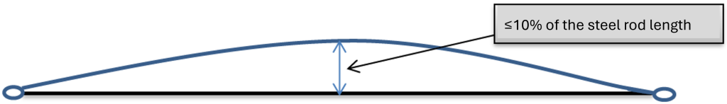
7.3.4 Tolerances for bending of steel rods
The length of the steel rod in the load bearing structure is allowed to be bent ≤10%. Hence, if the rod is 2.6 m, a bending of ≤26 cm is tolerated. If the rod gets in contact with the floating pipes, the rod must be replaced.
7.4 Inspection and maintenance of pen
| Area/ component | Check point | Method (GVI/NVI/ DC/MR) | Description of inspection | Spec. | Mthly. | Yearly |
| Floating pipes | Checked for damage and wear | GVI | Check floating pipes for cuts, cracks* and breakage | All floating pipes | X | X |
| Mooring brackets | Integrity of brackets | GVI | Check if mooring lug ear is bent or has a breakage | All mooring brackets | X | X |
| Mooring brackets | Integrity of brackets | GVI / NVI | Check mooring brackets with bushings for deformations. | All mooring brackets | X | |
| Steel and plastic brackets | Integrity of brackets | GVI / NVI | Check brackets with bushings for deformations/cracks | All relevant brackets | X | |
| Handrails/ handrail posts | Possible defects/damages | GVI / NVI | Check for breakage in handrails. Check handrail posts for damages. | All handrails and handrail posts | X | |
| Steel rod system/chain | Integrity of load bearing structure | GVI / NVI / MR | Check if rod/chain/rope in load bearing system is tight and free for deformation or breakage. The load bearing system MUST be retightened 3 months after the new pen is installed at the site. *This is followed by retightening during the yearly control if necessary. | Check the entire load bearing structure | X | X |
| Rod bolt/nut | Possible defects/damages | GVI / NVI | Check if rod bolt/nut in the load bearing structure is intact. REPLACE BOLT AND NUT IF ANY BOLTS ARE LOOSE. | All bolts/nuts | X | |
| GVI = General Visual Inspection NVI = Near Visual Inspection DC = Dimension Control MR = Modification/ Replacement |
*If the distance between 2 brackets has decreased by more than 20%, rods on the opposite side of the pen must be replaced with chain. This chain must be tightened until the chain on the opposite side is tight.
7.4.1 Retightening of chain in the load bearing system at sea
Reasons for why it is important to maintain tight chains in the load bearing system:
- Reduce the amount of bent steel rods that must be replaced.
- Extend the lifetime of steel rods and rod bolts by reducing the wear of these components over time. This can delay the time when the material thickness no longer fulfills the requirements.
- Movement in brackets due to slack in the chains brings more wear to bushings which can accelerate the need for replacement of bushings.
- Reduce the wear of brackets coming from steel rods and rod bolts.
Retightening should preferably be carried out during wintertime due to shrinkage in the plastic material during low temperatures which can cause slack in the chain.
For tightening of chain at sea, the following method should be used:
- Remove sufficient amount of walkway grates for access to the area where the chain is located.
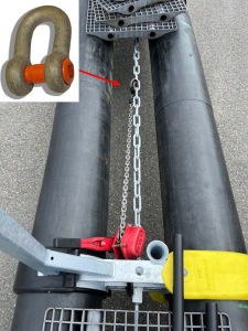
- Attach a 3.2-6 ton chain hoist to the steel flat bar on one of the brackets connected to the chain being tightened and the other end of the chain hoist to one of the chain loops a little more than half the distance to the bracket on the opposite side of the chain. See Figure 30.
- Tighten the chain hoist sufficiently for removing the chain slack. Perform an inspection round on the pen to check that other potential chain slack has disappeared.
- Connect the chain loops by using a min. 6.5 ton shackle with square-head bolt (article no. 301611 at ScaleAQ is recommended, use loctite thread fastener – medium strength). Consider attaching the leftover part of the chain (the slack that has been removed) to the tight chain to keep it above the water level. Shackle with bolt shown in the left corner in Figure 30.
Extra information:
- Do not use shackle with nut and locking cotter pin due to the risk of damaging the netting if it is hitched by the pin.
- If there is significant slack in the load bearing system, it is recommended to distribute the tightening across multiple chains. The maximum allowable tightening is 50 cm relative to the rod length. The more this tightening – up to a maximum of 50 cm – can be distributed across multiple points, the better it will be for avoiding uneven attachment of the net.
If a new chain is replacing a bent steel rod, the two following bullet points must be done before continuing with the tightening method already described.
- Remove enough walkway grates to access the brackets on each side of the steel rod being replaced with a chain.
- Remove rod bolts and the bent steel rod and fasten the chain as tight as possible with new rod bolts.
The person doing the inspection and maintenance must have internal training and know the product and the user manual. After periods with extreme weather, minimum one control each month must be carried out.
7.5 Generation control
A generation control can be carried out when it is the most convenient time before restarting each new production cycle when there is no fish in the pen. The pen cannot be used for longer than 24 months before a new generation control takes place. It is recommended that the control is carried out as close to the new production cycle as possible.
| Area/component | Method (GVI/NVI/DC/MR) | Description of inspection | Type of error | Comment | ||
| 0 | 1 | 2 | ||||
| Identification | GVI | Control that the floating collar has readable information and is identical with the number engraved in the middle mooring bracket. If the engraved number is not readable, the number must be engraved again. | ||||
| Mooring bracket | GVI / NVI | Control if there is formation of cracks, corrosion and wear. | ||||
| Mooring lug ear | GVI / NVI / DC | Control if there is deformation, formation of cracks, wear and tolerances for wear. | ||||
| Load bearing system | GVI / NVI | Control steel rods for wear and deformation (bending). Control steel chains for slack. *Retighten the load bearing system if there is slack in the chains. This can be done by using e.g. a chain hoist on the chains. | ||||
| Rod eyes / Rod bolts / nuts | GVI / NVI / DC / MR | Random measurement of 4 rods and rod bolts in crossed positions: disassemble and check for corrosion and tear. Check that all nuts are tightened. Check for wear and tolerance for wear. | For U-bolt rods: First random measurement 6 years after the pen or rod system was built/replaced, followed by every generation control. For forked rods: First random measurement 10 years after the pen or rod system was built/replaced, followed by every generation control. | |||
| Steel chain for tightening | GVI / DC | Inspect all steel chains in the load bearing system for tear and wear. Perform a dimensioning inspection of chain loop with most wear on every chain. | Performed at each generation control. | |||
| Plastic bushings in brackets | GVI / NVI | Look for wear and tear. Steel brackets must not touch the floating collar pipes. | ||||
| Damage to floating pipes | GVI / NVI | Check that floating collar pipes are not damaged due to tear or other mechanical stress. Check for wear and tolerance for wear. | ||||
| Brackets | GVI / NVI | Check for deformation and damage. Check that chain hook is intact. | ||||
| Sinker tube suspension | GVI / NVI | Check that correct locking cotter pin and securing shackle is being used. | ||||
| Loose chain pipes | GVI / NVI | Control and tighten bolts on loose chain pipes. | ||||
| Fenders | GVI / NVI / MR | Control and install new if needed. | ||||
| Walkway | GVI | Control that walkway grates are intact. | ||||
| Handrail | GVI | Control that handrails are intact. | ||||
| GVI = General Visual Inspection NVI = Near Visual Inspection DC = Dimension Control MR = Modification/Replacement | 0 = nothing to comment 1 = evaluation of improvement / replacement during the next 24 months 2 = immediate improvements needed |
*If the space between 2 brackets has decreased by more than 20%, the steel rod on the opposite side of the pen must be replaced with chain. This chain is tightened to a level where the chain on the opposite side of the pen is tight. See Figure 30.
7.6 Warranty steel rod system
7.6.1 Warranty terms
ScaleAQ offers a 10-year warranty on our load bearing steel rod system. The warranty covers components of the rod system such as rods, chains and bolts.
If any of the mentioned components experience failure or wear beyond the tolerance criteria specified in Section 7.3 within 10 years from the pen’s production date or the installation of a new rod system, ScaleAQ will replace the affected components free of charge.
Please note that the owner of the pen is responsible for any labor associated with the replacement of components.
7.6.2 Warranty conditions
For the warranty to be valid, the following conditions must be met:
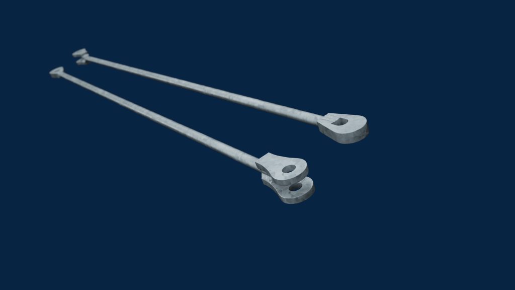
- The latest version of the steel rod system (forked rods) must be installed, see Figure 31.
- The user must be able to document that the operation and maintenance of the steel rod system is in accordance with the guidelines given in this user manual.
- The warranty period starts from the production date of the pen or from the documented installation date of a new steel rod system on the pen.
ScaleAQ encourages all users of FrøyaRingen pens to follow the user manual and the inspection and maintenance program in Section 7 in order to ensure maximum performance and lifetime of the steel rod system.
8. Transport and storage
8.1 Transport/towing
For transport/towing of pen with sinker tube lying on top of the walkway, guidelines for securing the sinker tube must be followed. These are listed below.
- Check if it is necessary to apply for towing authorization of floating collars.
- Pen must be towed without the net.
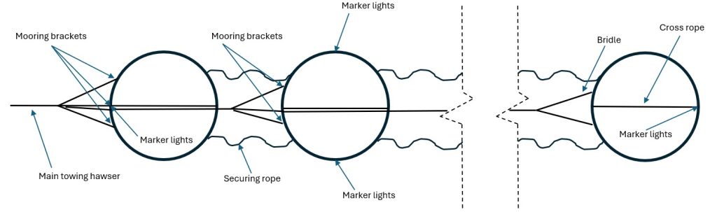
- The pen is connected to the towing hawser by a bridle with a distance of ca. 20m. The bridle is attached to the pen’s mooring brackets. ScaleAQ recommends attachment to three mooring brackets for the first pen in the towing line and minimum two attachment points for the rest of the pens.
- When towing multiple pens, the towing hawser runs through the bridle attached to the first pen to the bridle attached to the last pen.
- During towing, the towing hawser must have free passage through the pens. This is most easily done by running the hawser through loops/rings that are attached to separate brackets. See Figure 33.
The length of the towing hawser from the towing boat to the first pen should be minimum 150m to reduce the impact of ship wake (turbulent water behind the boat).
- In case anything happens to the towing hawser or bridles, ScaleAQ recommends securing the towing hawser with slack ropes on each side parallell with the main hawser. See “redundancy securing rope” in Figure 34.
- To prevent irregular deformation of the floating collars, a rope should be attached in the towing direction between inner floating collars. See “cross rope” in Figure 34.
- All knots and ropes should be secured with two inserts and seized.
- If the pen has a sinker tube, it can be secured on top of the walkway during towing as shown in Figure 32. More information about this in the user manual for sinker tube suspension.
- If towing is performed with the sinker tube attached under the floating pipes, make sure that the sinker tube suspension, pen and/or sinker tube is not exposed to damage.
- Relative towing speed must not exceed 3 knots.
- Maximum allowed Hs=1,5m.
- Maximum 15T for the main towing hawser.
- During transport of pen with net, the speed must be adjusted for the currents/waves in order to stay within the pen’s max. allowed significant wave height and current.
After the towing is finished, the pen must be inspected for potential damage. ScaleAQ has prepared a specific procedure for the towing of pen with a check list/control form.
8.2 Storage of pen at sea
During storage at sea, the pen must be properly moored and marked for third-party traffic. It is preferred that the pen is placed in sheltered water during the storage period. If multiple pens are stored together, they must be moored in a way that prevents them from touching each other and cause potential damage.
During temporary storage, the pen must be moored in the bridle attachment points diagonally as a minimum. It is recommended to attach the pen to the frame anchoring to use all bridle sets (min. 1 bridle in each set).
8.3 Storage of pen on land
For storage of pen on land, it is important that the ground is flat for avoiding “sharp objects” where point loads can perforate the floating collar pipes, or damage fenders and other hardware.
9 Manufacturer and product identification
| HEAD OFFICE | |
| Scale Aquaculture AS | Phone: +47 73 80 99 30 |
| Beddingen 16 | E-mail: post@scaleaq.com |
| 7042 Trondheim | www.scaleaq.no |
| CONTACT INFORMATION | flytekrage@scaleaq.com |
9.1 Documentation
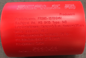
Pens from ScaleAQ have a product certificate with information about the dimension class, validity period and details about the pen and the materials it is made of. The product certificate must be available at the company keeping the aquaculture permission. See example in attachment 1.
9.2 Identification of pen
Each pen has a unique serial number identifying the products. The pen is marked with a unique marking tube in plastic.
10 Revision history
| Revision | Change | Date |
|---|---|---|
| 1 | The user manual is revised to meet new requirements in NS 9415:2021. | 30.12.2024 |
| 2 | Added two more types of brackets in Section 2.1. Added Section 5.2 Recommended frame size in mooring system. Changed Section 7.5 Generation control and first measurement of steel rod bolt and nut from 6 to 10 years. Added Section 7.6 Warranty forked steel rod system. | 26.05.2025 |
11 References
| /1/ | NYTEK23 |
| /2/ | NS9415:2021 |