Manuals
Electrical cabinet module

Explanation of symbols
Important information is labelled with the following symbols:

1 Summary with an overview of the component and key points related to escape protection
1.1 General definitions
| Aquaculture farm | Installation for the farming of fish. |
| Basin dimensions | The pen’s inner circumference. |
| Design working life | Assumed period for which a structure or part of it is to be used for its intended purpose with anticipated maintenance but without major repair being necessary. |
| Operation | Fish farming at site, including all installation and operation activities performed at the site while fish farming is in progress, and that are of relevance to the escape prevention of fish. |
| Extra equipment | Equipment that is not a main component. |
| Inspection | Systematic inspection/examination, usually visual, to ensure that the equipment satisfies the requirements. |
| Pen | Structure whose main function is to provide an enclosurewith buoyancy and/or stiffness. |
| Anchoring system | System of lines and bottom attachments with the main function of keeping the aquaculture farm or raft in position. |
| Bridles | Anchoring line between the pen and the anchoring system. |
| Main component | Part of an aquaculture farm that holds one or more of the installation’s load bearing main functions. Example: Pen, anchoring system, raft and enclosure. |
| Enclosure | Net or other system of load bearing parts that form a barrier between the farming volume in a production unit and the surrounding water volume. |
| Bracket | Component keeping the inner and outer floating collar pipes together. |
| Sinker weight | Weight or other device attached to the net to achieve the intended shape. Sinker weight/Centre weight is attached beneath the bottom centre of the net-cone. |
| Cage | Pen with enclosure. |
| NS9415:2021 | Standard which sets out functional requirements for floating aquaculture farms and will be fundamental for stakeholders in the aquaculture industry, such as authorities, supervisory bodies, designers, suppliers, actors within R&D and manufacturers, as well as aquaculture farm owners. |
| NYTEK23 regulation | Governing Regulation for Fish Farming in Norway. |
| Circumference | Inner length of the inner floating collar. |
| Product certificate | Document confirming that the product is manufactured in accordance with the requirements of NYTEK23 and NS9425:2021. |
| Suspension system | Weights, bottom rings or similar to help maintain the three-dimensional shape of the net. |
1.2 Introduction
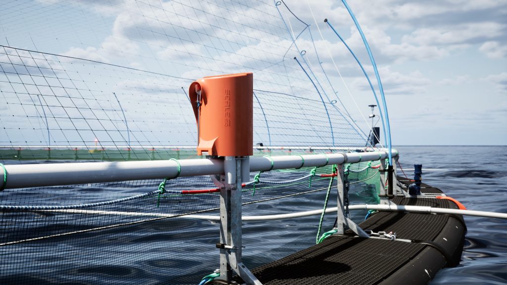
The electrical cabinet module protects electrical cabinets for controlling e.g. Midgard winches, cameras and lights on the cages from water intrusion and ensures solid mounting of the electrical cabinet to the cages. The colour makes it highly visible.
2 Interaction with other components
The electrical cabinet module fits ScaleAQ’s universal bracket for extra equipment and is designed to fit electrical cabinets with sizes up to 400x400x200 mm.
3 Installation of the unit
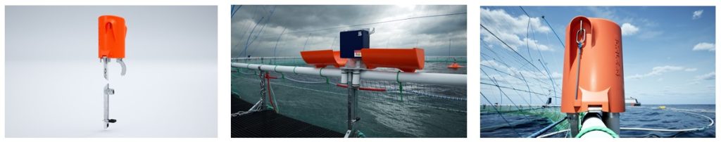
The vertical bracket in the electrical cabinet module is threaded into the universal bracket and mounted with bolts. The U-shaped/curved bracket is threaded around the handrail and secured with bolts in the universal bracket. The electrical cabinet itself can be attached to the steel plate in the electrical cabinet module both before and after the unit is mounted on the pen.
The cables are covered by the cable protectors as shown under the steel plate in the centre photo in Figure 3.1. The two orange plastic covers are closed by threading a steel ring fastened with a tight elastic band over a hook on both sides of the vertical steel plate to which the cabinet is attached.
4 Installation on site
The electrical cabinet module can be easily installed on site and the power box can be replaced when needed when the plastic cover is in the open position.
5 Use
The electrical cabinet module can be used on all pens that have ScaleAQ’s universal bracket installed.
6 Inspection and maintenance
A weekly visual check of the module both inside and outside is recommended to ensure that:
– There are no cracks in the plastic cover that could lead to water intrusion
– The elastic band used to close the plastic covers in vertical position is still tight
– There is no chafing of cables against the steel plate
– All bolts and nuts are still tight
7 Transport and storage
When assembled on site, the parts for the electrical cabinet module are packed as general cargo/europallets. The parts consist of the bracket, U-brackets, steel plate, plastic covers, a package with fastening equipment and cable protection.
8 Manufacturer and product identification
The electrical cabinet module is labelled with ScaleAQ’s logo.
9 Revision history
| Auditing | Changes | Date |
|---|---|---|
| 1 | The user manual is designed to meet new requirements in NS 9415: 2021. | 26.04.2024 |